Chamfering tool dedicated for porous inside

A technology of chamfering and cutting tools, which is applied in the field of special cutting tools for chamfering in holes, can solve the problems of high processing experience requirements, difficulty in mass production, high probability of waste products, etc., achieve simple and fast conversion operations, improve processing efficiency, The effect of shortening the processing time

Inactive Publication Date: 2007-05-30
CHONGQING LIFAN INDUSTRIAL (GROUP) CO LTD
View PDF0 Cites 6 Cited by
  • Summary
  • Abstract
  • Description
  • Claims
  • Application Information

AI Technical Summary

Problems solved by technology

[0006] 1. The transition between the working state and the non-working state of the chamfering blade is complicated, and it is completely done by hand, especially after the lower part of the chamfering tool rod is inserted into the hole, and before the chamfering process, due to space and line of sight, the blade must enter the working state Manual manipulation is difficult when
[0007] 2. When the blade is in a floating state, it is easy to shake, the surface quality of the chamfer is difficult to guarantee, and the probability of waste products is high; on the other hand, the blade is prone to damage
[0008] 3. The operation is complicated, and the processing experience of the operator is quite high, so it is difficult to form mass production

Method used


Image

  • Chamfering tool dedicated for porous inside
  • Chamfering tool dedicated for porous inside

Examples


Embodiment Construction

[0022] Below in conjunction with accompanying drawing and embodiment, the present invention will be further described:

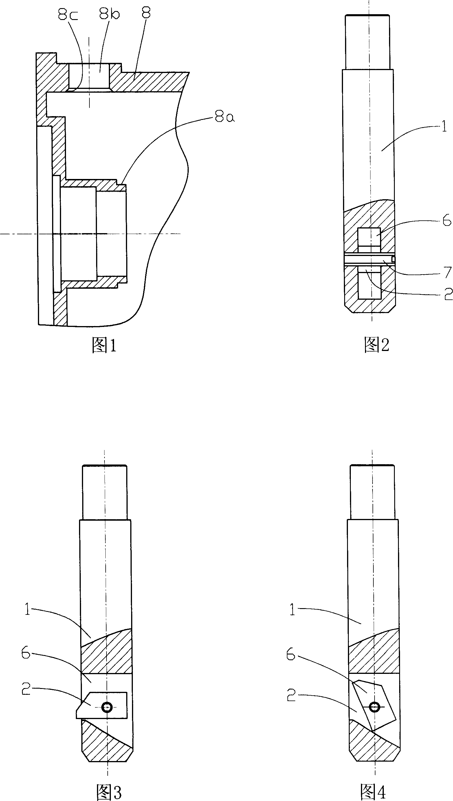
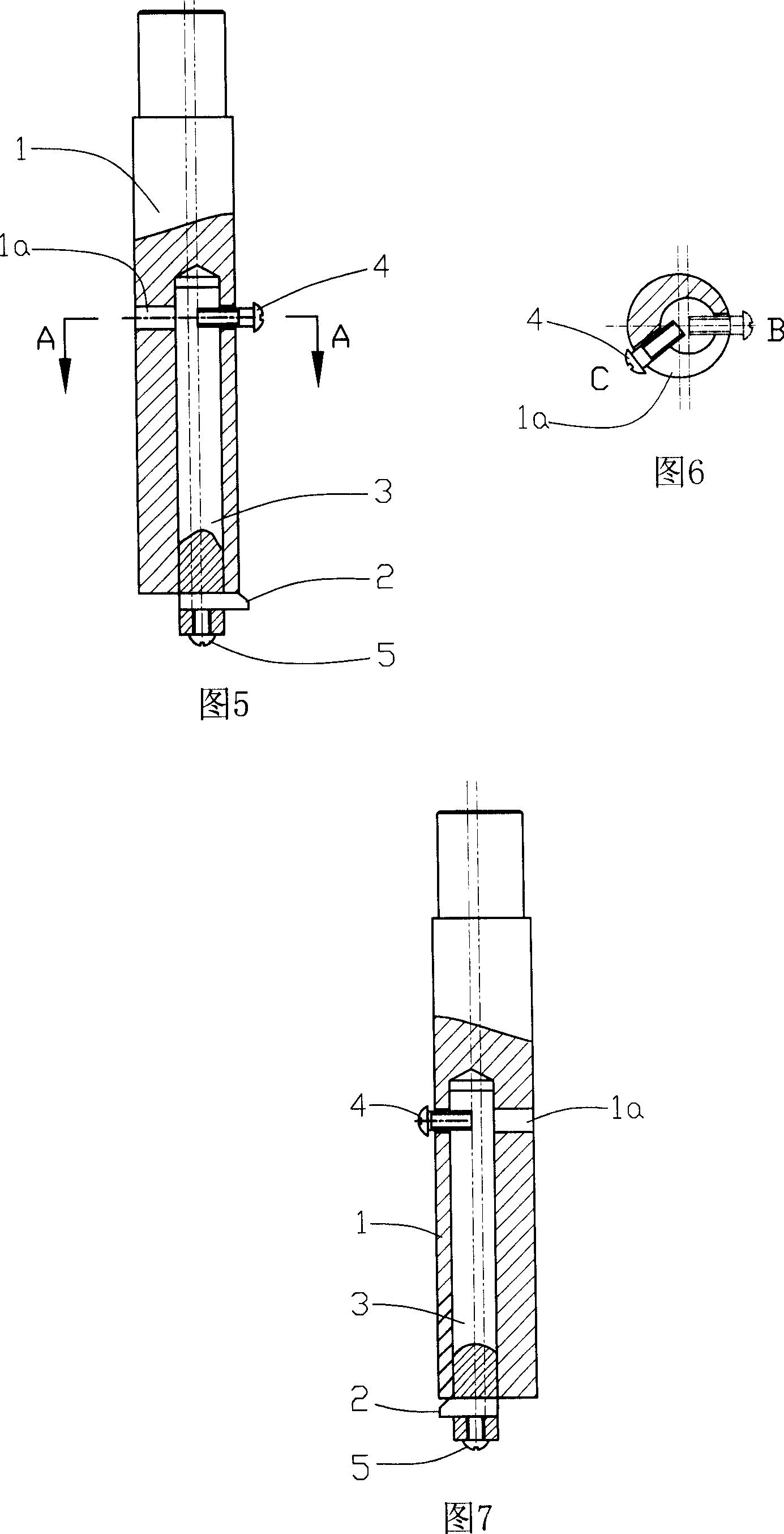
[0023] As shown in FIG. 5 , FIG. 6 and FIG. 7 , the present invention is composed of a first cutter bar 1 , a blade 2 , a second cutter bar 3 , a toggle screw 4 , and a tightening screw 5 . The bottom surface of the first tool bar 1 is provided with an eccentric hole along the direction of its axis line, and the center line of the eccentric hole is deviated from the axis line of the first tool bar 1 . In the middle of the outer circumference of the first cutter bar 1, there is a shifting groove 1a which communicates with the upper part of the eccentric hole. A second cutter bar 3 is installed in the eccentric hole, the second cutter bar 3 and the first cutter bar 1 are gap-fitted, and a blade is installed at the position where the lower end of the second cutter bar 3 protrudes from the bottom surface of the first cutter bar 1 A square hole, the blade 2 is l...


PUM

PropertyMeasurementUnit
angleaaaaaaaaaa

Abstract

A inner hole chamfer tool with eccentric hole along the axial center line at the bottom of the No.1 knife bar with No.2 knife bar in the eccentric hole, bottom of the lower part of the No.2 knife bar stretching to the bottom of No.1 knife bar to install blade, shifting screw's outside end going through the shift groove of the outside circumference of the No.1 knife bar loaded on the No.2 knife bar, driving the relevant rotation of No.2 knife bar opposite to No.1 knife bar when the shift screw moves inside the shift groove. With the chamfer blade shifting outside the shell of the part either working or unworking, it is simple and quick in operation, with shortened time, improved efficiency, suitable for mass production, free from shaking of the chamfer blade in working to avoid the damage of blade and ensuring the quality of the chamfer surface.

Description

technical field [0001] The invention relates to a special tool for chamfering in holes, which is used for chamfering in holes of shell parts. Background technique [0002] The structure of the motorcycle engine left crankcase cover is shown in Figure 1. The cover body 8 is provided with a magneto stator assembly mounting step 8a, and the cover body 8 is provided with a through hole 8b for the output wire of the magneto stator assembly to pass through. There is a rubber sealing plug on the output wire of the magneto stator because there is organic oil in the left crankcase cover. In order to facilitate assembly and ensure sealing, the lower part of the through hole 8b on the left crankcase cover shown in FIG. 1 requires a chamfer 8c. Generally speaking, the aperture size of the through hole 8b on the left crankcase cover of the motorcycle engine is φ14mm, and the chamfer 8c at the lower part of the through hole 8b is 1.5mm×45°. The machining method of the outer chamfering o...

Claims


Application Information

Patent Timeline
Patent Type & Authority Applications(China)
IPC IPC(8): B23B27/06B23B29/12B23B5/16
Inventor 尹明善王胜华
Owner CHONGQING LIFAN INDUSTRIAL (GROUP) CO LTD
Why Eureka
Try Eureka