
Tire condition monitoring system

A monitoring system and tire technology, applied in tire measurement, tire parts, signal transmission systems, etc., can solve the problems of short replacement cycle of built-in batteries and high power consumption, and achieve the goal of suppressing large-scale, improving reliability, and suppressing costs Effect

Inactive Publication Date: 2007-06-06
PACIFIC INDUSTRIAL CO LTD
View PDF1 Cites 6 Cited by
  • Summary
  • Abstract
  • Description
  • Claims
  • Application Information

AI Technical Summary

Problems solved by technology

[0004] However, in the above-mentioned conventional tire condition monitoring system, since the power consumption accompanying radio wave output is large, there is a problem that the built-in battery of the tire side communication device is enlarged, or the replacement cycle of the built-in battery is short.

Method used


Image

  • Tire condition monitoring system
  • Tire condition monitoring system
  • Tire condition monitoring system

Examples


Embodiment Construction

[0029] Hereinafter, an embodiment of the present invention will be described with reference to FIGS. 1 to 5 .

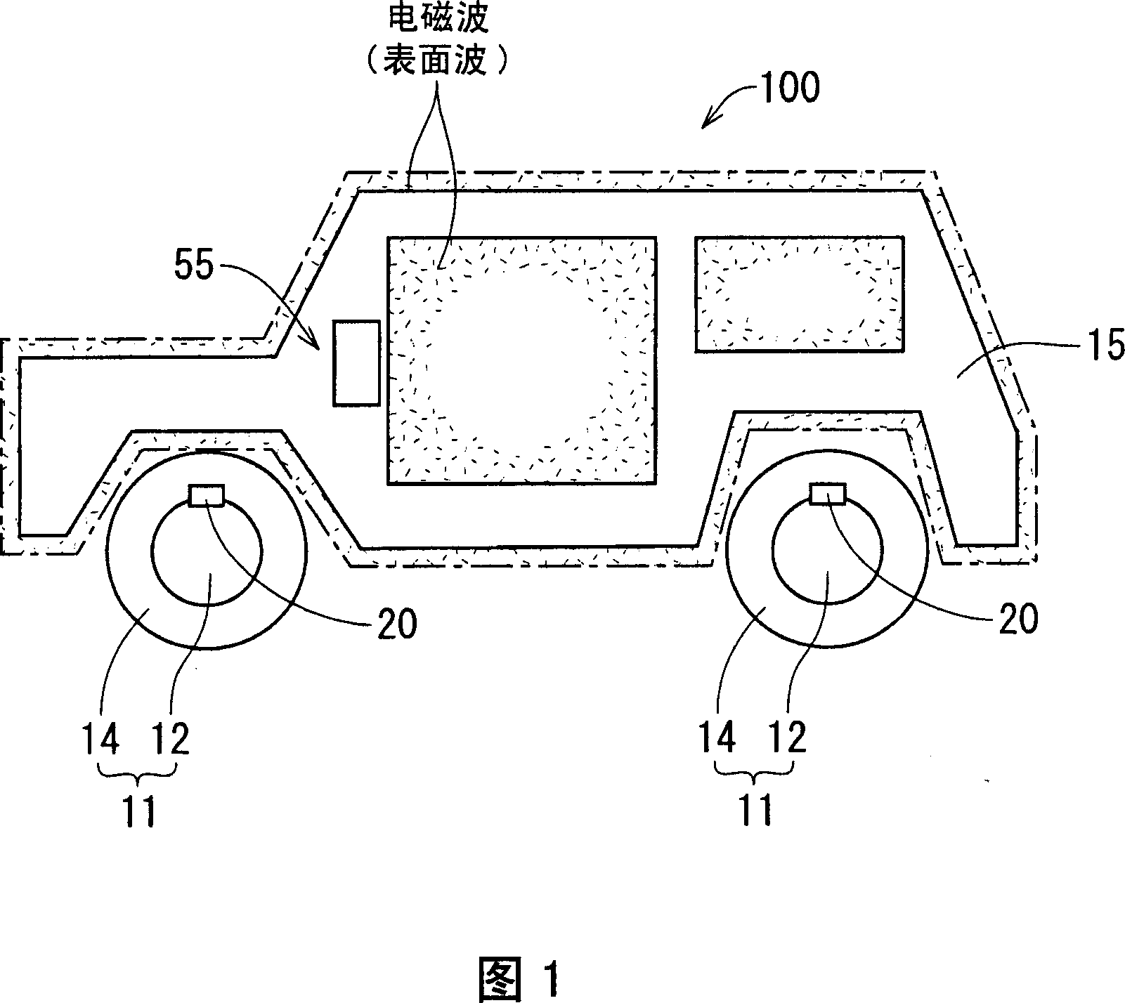
[0030] The tire condition monitoring system 10 of the present embodiment has: for example, four tire-side communicators 20 mounted on an automobile 100 and fixed to four wheels 11 (only two of which are shown in FIG. 1 ); One vehicle body side communicator 55 equipped on the vehicle body 15 of the vehicle.

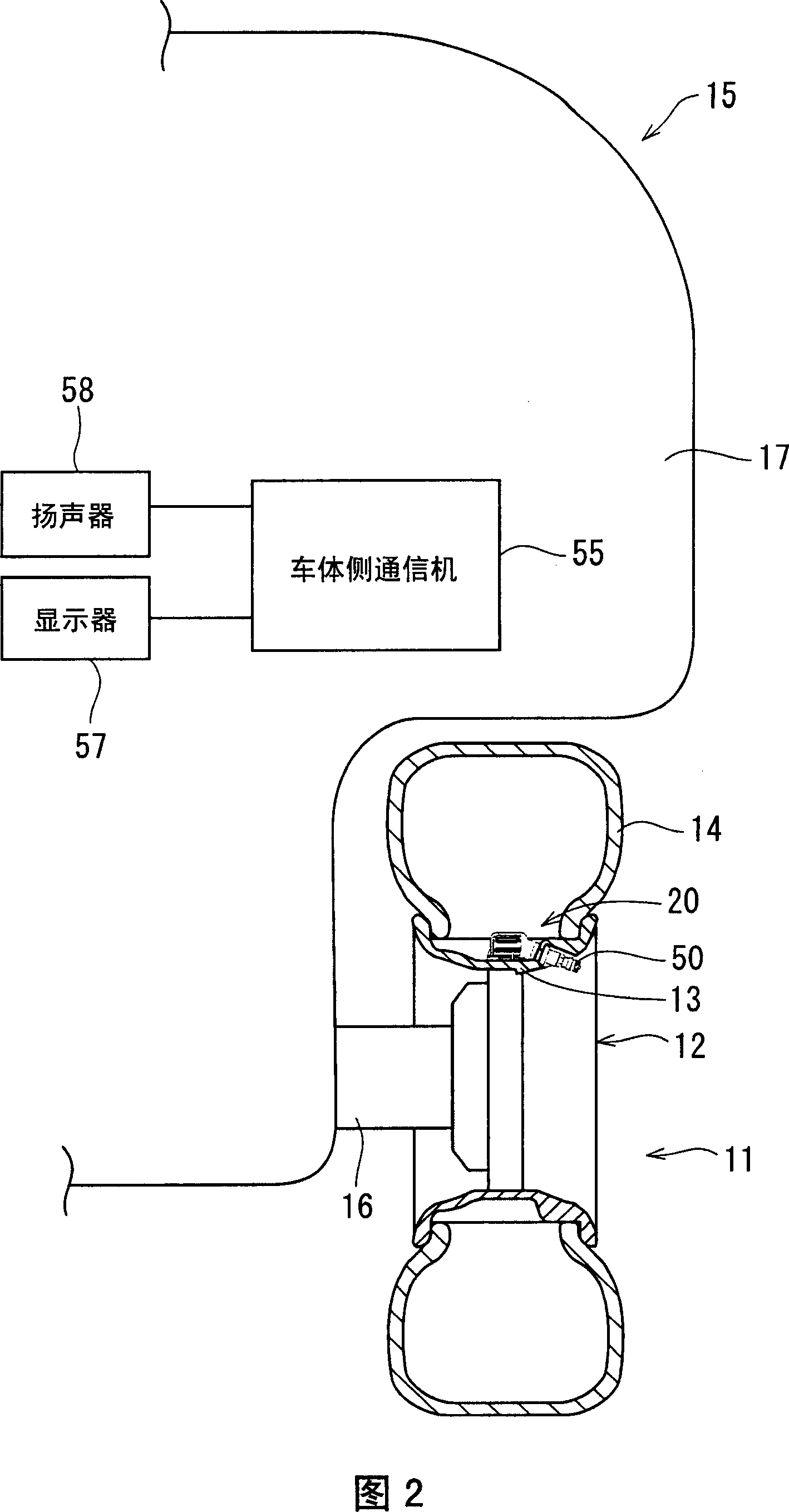
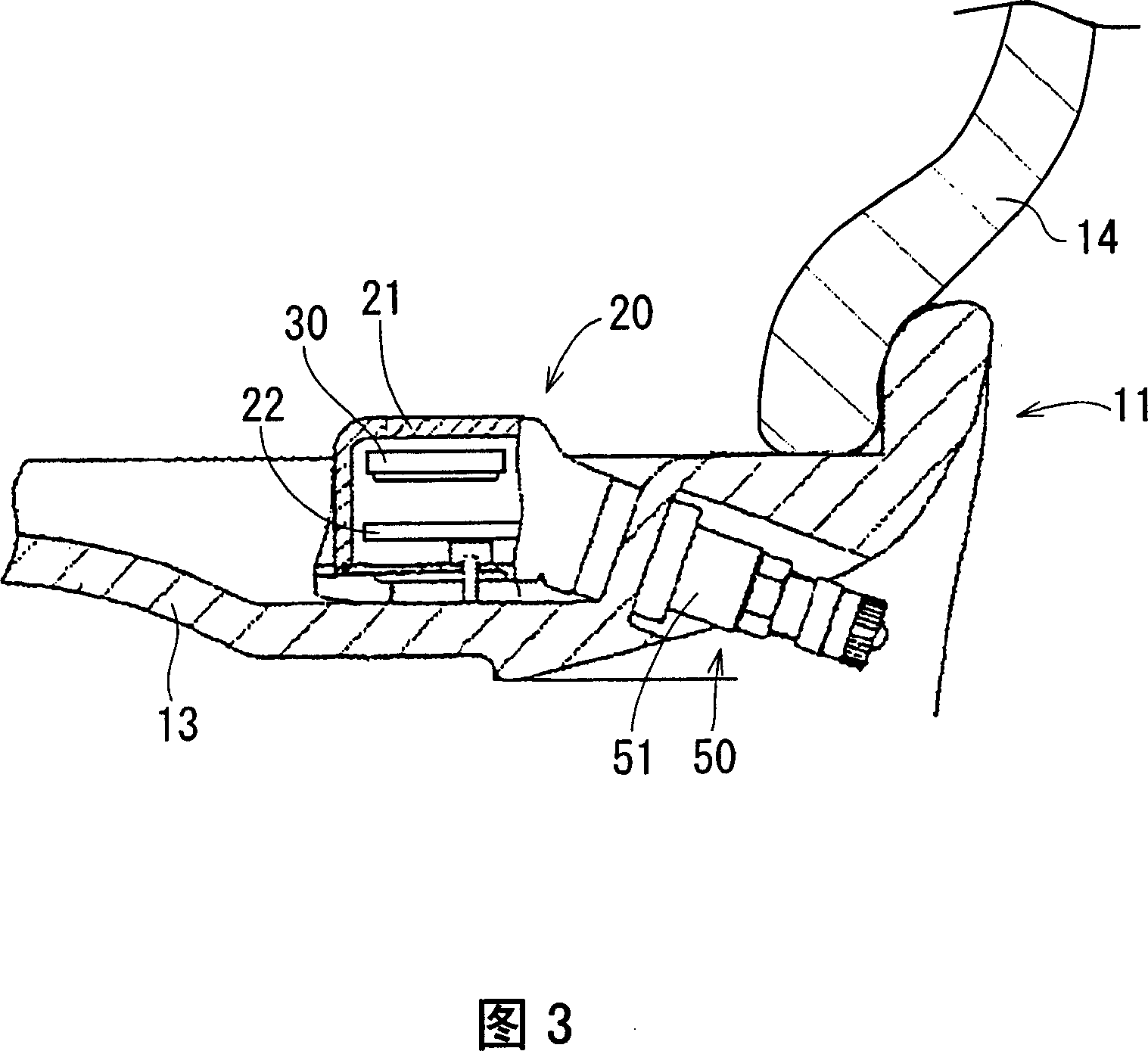
[0031] As shown in FIG. 2 , the tire side communicator 20 and the metal tire valve 50 are integrally equipped. The opening of the inner peripheral surface of the tire 14 equipped on each wheel 11 is blocked by the bead 13 covering the wheel 12, whereby the inside of the tire 14 becomes a closed space. The tire valve 50 is fixed so as to pass through the widthwise middle portion of the bead 13 inside and outside, and the tip end of the tire valve 50 is drawn out from the bead 13 to the side opposite to the vehicle body 15 . Further, in the tire-side communicatio...


PUM


Abstract

The object is to provide a tire condition monitoring system in which power consumption upon output of information by the tire side communication device can be reduced as compared with the conventional tire condition monitoring systems. According to the present inventive tire condition monitoring system 10, the tire side communication devices 20 superimpose detection information on the electromagnetic waves, delivering the electromagnetic waves as surface waves of the tire wheel 12 and vehicle body 15. Accordingly the power comsumption in output of information can be reduced as compared with the conventional tire condition monitoring systems. Consequently, the size of the microcell 30 used in the tire side communication device 20 can be downsized and the life of the microcell 30 can be longer. More specifically, the tire condition monitoring system 10 of the embodiment consumes -10 dBm (0.1 mW) at the time of information output although a conventional system consumes 3 dBm (2 mW). Thus, the power consumption in inforrmation output can be reduced to one twentieth of that of the conventional system.

Description

technical field [0001] The present invention relates to a vehicle equipped with a tire-side communicator mounted on a tire cover wheel for detecting tire internal pressure and wirelessly outputting information including the detection result, and a vehicle mounted on a vehicle body for wirelessly receiving the information wirelessly output by the tire-side communicator The tire condition monitoring system of the main body side communicator. Background technique [0002] In such a conventional tire condition monitoring system, the tire side communicator transmits the tire internal pressure on radio waves to the vehicle main body side communicator (for example, refer to Patent Document 1). [0003] Patent Document 1: JP-A-2005-212514 (paragraph [0021]) [0004] However, in the above-mentioned conventional tire condition monitoring system, since the power consumption accompanying radio wave output is large, there is a problem that the built-in battery of the tire side communica...

Claims


Application Information

Patent Timeline
Patent Type & Authority Applications(China)
IPC IPC(8): G08C17/02B60C23/00
CPCB60C23/0433B60C23/0444B60C23/0494
Inventor 大久保阳一川濑真一辻田泰久
Owner PACIFIC INDUSTRIAL CO LTD
Learn More