

Air conditioner AC machine driving method and circuit
A technology of AC motor and driving method, which is applied in the direction of AC motor control, motor vibration suppression control, motor parameter estimation/correction, etc. It can solve the problems that no longer meet the needs of global production, achieve good control and reduce production Cost, effect of preventing motor damage
Patent Information
- Authority / Receiving Office
- CN · China
- Patent Type
- Applications(China)
- Current Assignee / Owner
- Publication Date
- 2007-06-06
Smart Images
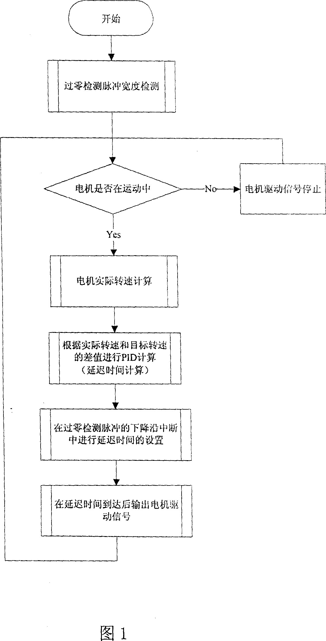
Figure 1 
Figure 2 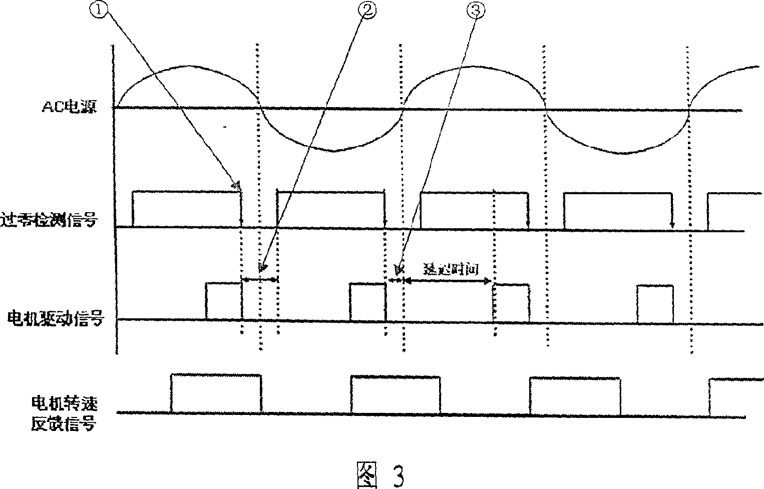
Figure 3
Abstract
Description
technical field
[0001] The invention belongs to the field of electrical appliances, in particular to an AC motor driving method and circuit, in particular to an air conditioner AC motor driving method and circuit. Background technique
[0002] With the improvement of people's living standards, household air conditioners are becoming more and more popular, and now the indoor fan control of household air conditioners usually uses an adjustable-speed AC motor. Compared with the tapped motor with constant speed, the adjustable speed AC motor has many advantages: low noise, energy saving, wide speed adjustment range, etc. However, it also has its disadvantages. The adjustable-speed AC motor is relatively expensive and the control method is relatively complicated.
[0003] In the existing adjustable-speed AC motor drive circuit for air conditioners, the hardware circuit, power supply and control software must be matched with each other, which is not universal. As long as any one...
Examples
Embodiment Construction
[0028] The process flow of the AC motor driving method of the air conditioner of the present invention is shown in FIG. 1 . First, the width of the zero-crossing detection pulse needs to be calculated in the initialization process, and the pulse width of the zero-crossing detection is shown in FIG. 3 as ②. Thereafter, the starting position of the motor drive is consistent with the falling edge of the zero-crossing detection pulse, as shown by ① in Figure 3. And in the actual calculation, it is necessary to increase 1 / 2 of the zero-crossing detection pulse width, as shown in ③ in Figure 3 . In fact, the starting position of the motor drive should start from the actual zero-crossing point of the power supply, but the zero-crossing detection pulse width obtained for different power supplies is different, so there is an error between the actual power supply zero-crossing point and the point where the zero-crossing detection interruption occurs . If the actual zero-crossing point ...