Optical coding/decoding device whose plane light-path is variable

A planar optical path and decoder technology, which is applied in the field of optical encoding and decoding, can solve the problems of non-adjustable, difficult to adapt to flexible configuration and adjustment of optical encoders, and scattered parameters, so as to overcome performance limitations and expand the use of functions and scope of use , The effect of reducing manufacturing costs

Inactive Publication Date: 2007-06-13
杨淑雯 +1
View PDF0 Cites 0 Cited by
  • Summary
  • Abstract
  • Description
  • Claims
  • Application Information

AI Technical Summary

Problems solved by technology

The basic components of optical communication such as encoders should be applied to large-scale integrated optical circuits. In the application of small batch equipment, the parameters of the PLC are scattered and cannot be adjusted. If the encoder needs to change the parameters slightly, the above encoder cannot meet the requirements.
[0003] The optical encoder with a single technical parameter is difficult to adapt to the flexible matching and adjustment of large-scale planar optical path PLC

Method used


Image

  • Optical coding/decoding device whose plane light-path is variable

Examples


specific Embodiment approach

[0016] [Description of Embodiments] The present invention will be further described below in conjunction with the accompanying drawings and embodiments.

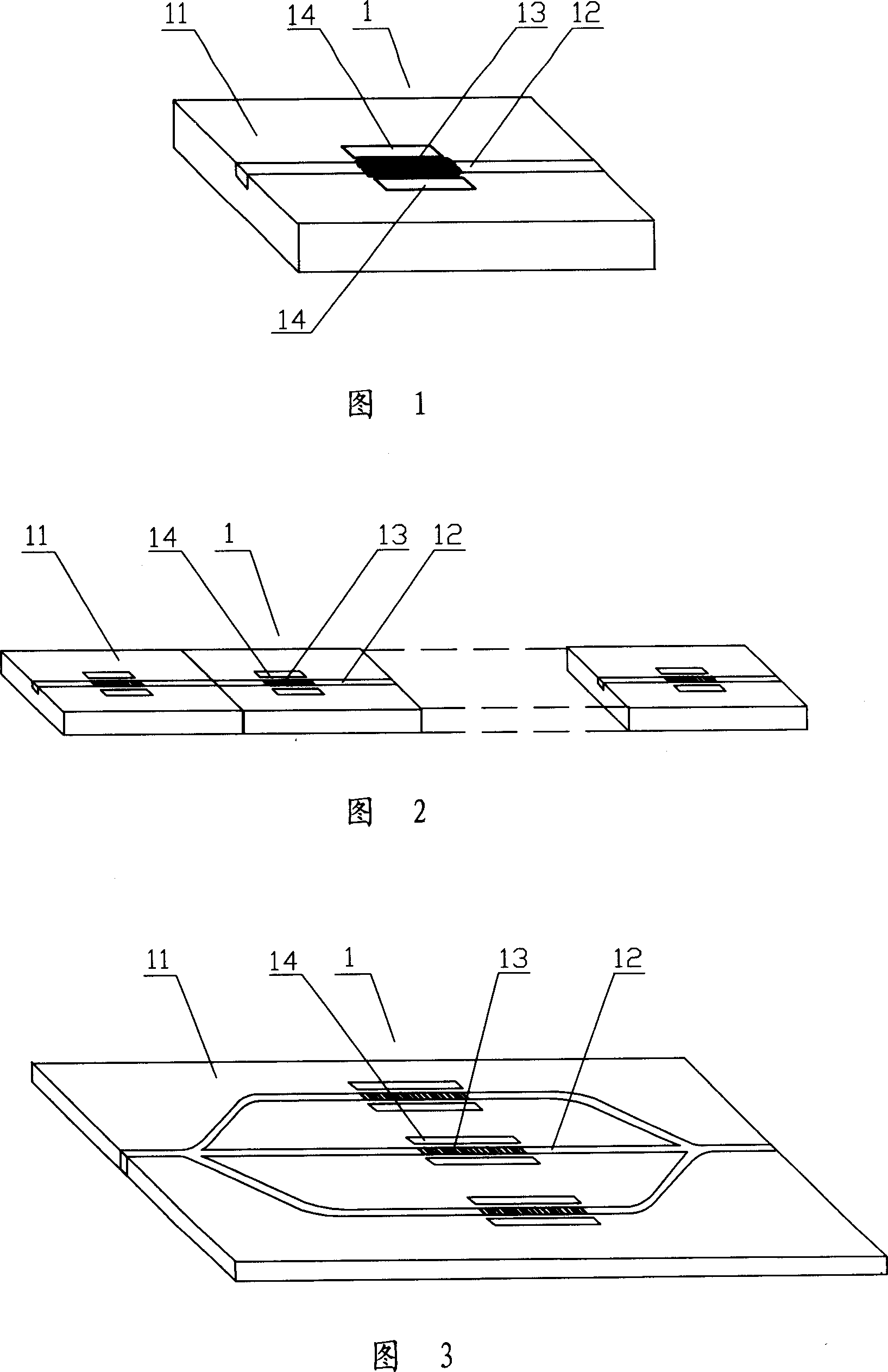
[0017] An optical encoder / decoder with a variable planar optical path, comprising at least one optical unit device 1; the optical unit device 1 includes a planar waveguide substrate 11 and an optical transmission waveguide 12 passing through the substrate 11; the transmission waveguide On the optical path, there is a grating 13 for encoding / decoding; the feature is that the grating 13 is a controlled variable parameter grating.

[0018] In some embodiments, an electromagnetic field control pole 14 is arranged near the grating 13 .

[0019] In other embodiments, a variable temperature control pole 15 is arranged near the grating 13 . The variable temperature control pole 15 may be an electro-semiconductor temperature controller. It can heat up or cool down with the change of voltage.

[0020] The substrate 11 is a dielectr...


PUM


Abstract

The invention proposes an optical encoder / decoder with variable plane light path, comprising at least an optical device which comprises plane waveguide substrate and optical transmission waveguide running through the substrate; the light path of the transmission waveguide is provided with an encoding / decoding grating; and the invention is characterized in that: the grating is a controlled, variable-parameter grating. And the invention has very good flexibility and practicality, increasing use functions and enlarging use range, and can cooperate better with large scale optical communication PLCs. And the beneficial effects: it improves use flexibility and practicality of optical communication equipment and simultaneously reduces total manufacturing cost.

Description

【Technical field】 [0001] The invention relates to optical transmission and optical conversion technology, in particular to optical coding and optical decoding technology. 【Background technique】 [0002] With the rapid increase of the amount of social information, the information infrastructure is required to have high bandwidth and high speed. The information network must evolve from the traditional circuit switching to overcome the electronic bottleneck and evolve into an all-optical network for transmission and switching in the optical domain. In the optical domain, the optical encoding and optical decoding are performed on the optical signal, the optical encoder implements optical encoding, and the optical decoder implements optical decoding. It is applied in the field of optical communication and all-optical network. The principle is that after the optical signal enters the optical encoder, it is coded and converted according to the preset parameters; and the optical cod...

Claims


Application Information

Patent Timeline
Patent Type & Authority Applications(China)
IPC IPC(8): G02B6/124G02B6/36
Inventor 杨淑雯马君显蒲涛张志朋吉建华徐铭吴迪严新民周建华王可
Owner 杨淑雯
Why Eureka
Try Eureka