Hollow basin

A hollow, basin-wall technology, applied to building components, floor slabs, buildings, etc., can solve the problems of high transportation costs, increased production costs of basin-shaped formwork components, construction costs of cast-in-place reinforced concrete hollow slabs, and large space occupation.

Inactive Publication Date: 2007-06-20
邱则有
View PDF3 Cites 1 Cited by
  • Summary
  • Abstract
  • Description
  • Claims
  • Application Information

AI Technical Summary

Problems solved by technology

Equally, this pot-shaped formwork member, as an integral member, also takes up a lot of space during transportation, the quantity of each transportation is small, and the transportation cost is high, which undoubtedly increases the production cost of the basin-shaped formwork member and the cast-in-place The construction cost of the reinforced concrete hollow slab, therefore, the development of a new type of hollow basin has been urgently needed

Method used


Image

  • Hollow basin
  • Hollow basin
  • Hollow basin

Examples


Embodiment Construction

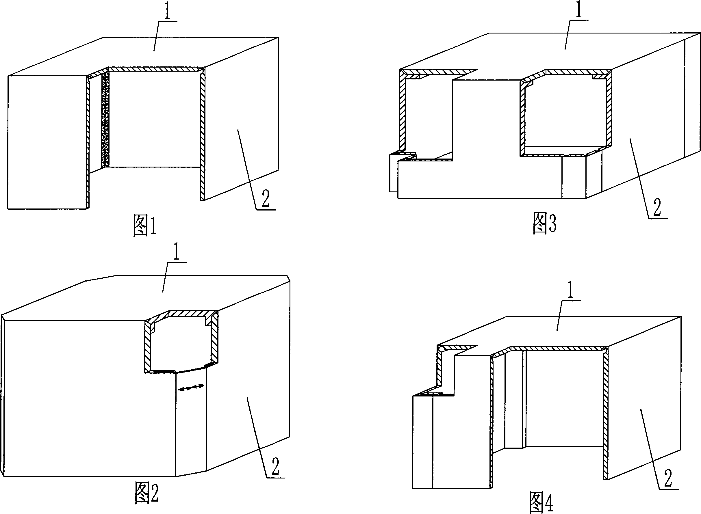
[0068] The present invention will be further described below in conjunction with the accompanying drawings and embodiments.

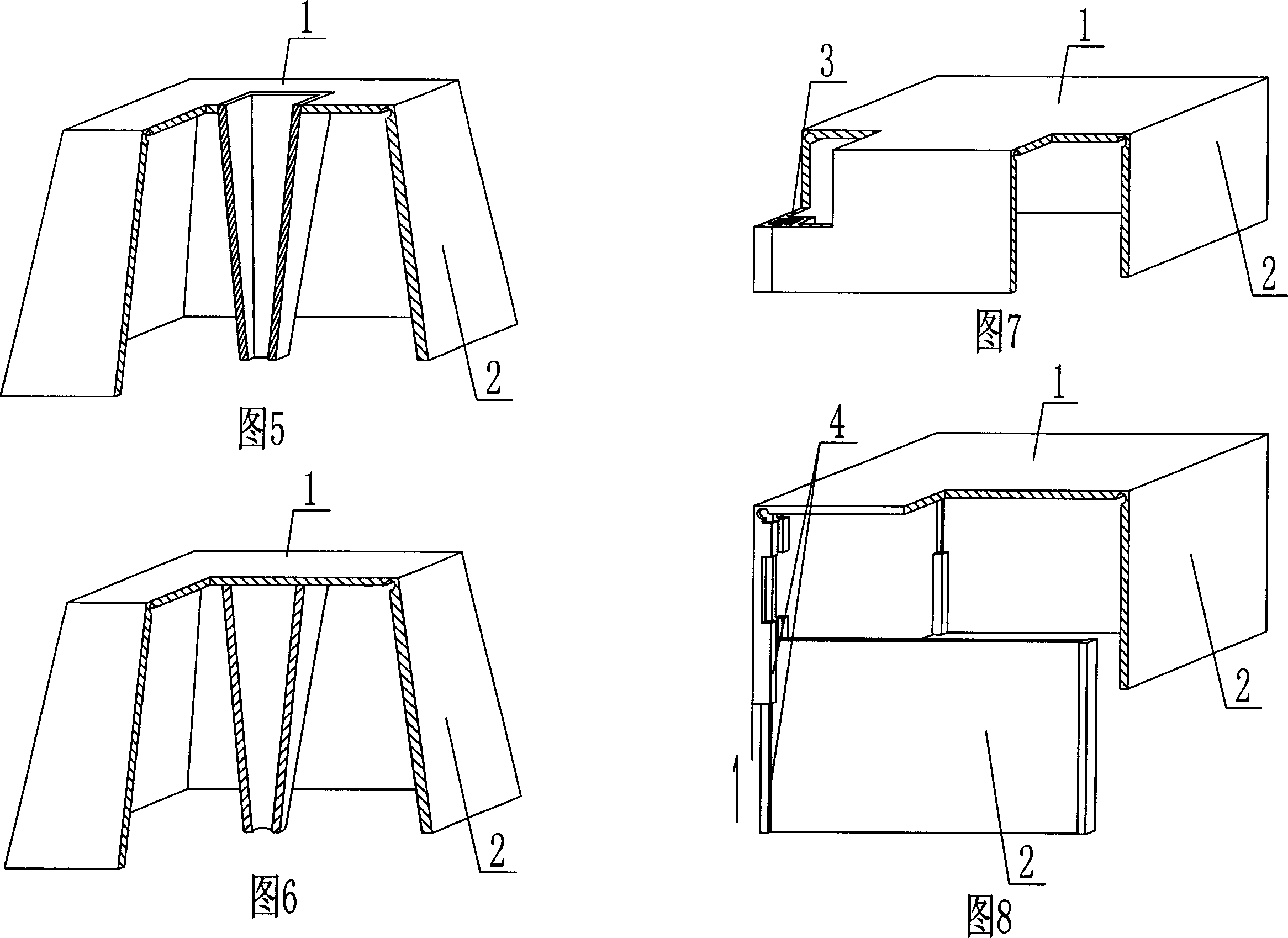
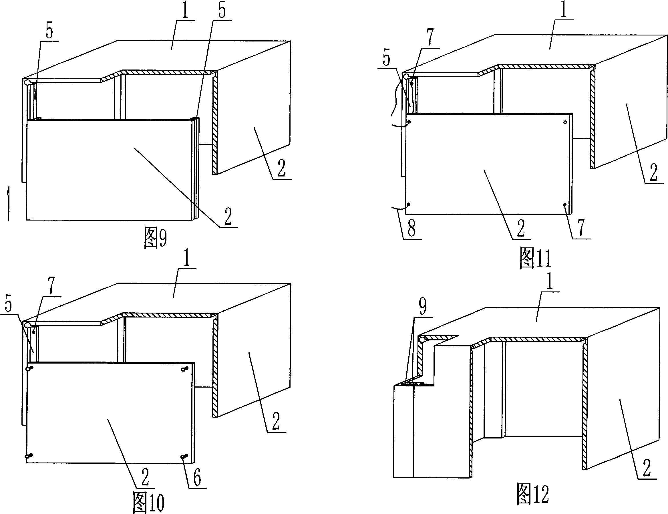
[0069] As shown in the accompanying drawings, the present invention includes a basin top plate 1 and a basin side plate 2, and is characterized in that at least two basin side plates 2 are integrated with the basin top plate 1, and the adjacent sides of the basin side plates 2 are connected to each other to form an annular basin wall , The pot top plate 1 and the annular pot wall form an open hollow pot, and the joint of the pot side plate 2 is a hinged connection. As shown in Figure 14, a plurality of pot side plates 2 and pot top plate 1 are integrated as a whole. 2 The connection is a hinged connection. As shown in Figure 15, a plurality of pot side plates 2 and pot top plate 1 are integrated as a whole. 2 The connection is a hinged connection.

[0070] The present invention is also characterized in that the open hollow basin has supporting feet 1...


PUM


Abstract

A hollow basin is composed of head plate(1) and side plate(2), Said head plate(1) is integrated with at least two side plates(2), adjacent edges of side plate(2) are connected into circular wall, said head plate and circular wall form into opening hollow basin, and side plate(2) joint is hinged connected. It can be used for various hollow plates of cast-in-situ reinforced concrete or pre-stressed reinforced concrete, hollow building roof, basic baseboard and wall.

Description

(1) Technical field [0001] The invention relates to a hollow basin. (2) Background technology [0002] At present, in the prior art, the hole-forming member of the cast-in-place reinforced concrete hollow slab is a permanent mandrel, such as paper tubes, plastic tubes, metal bellows, hollow form shells, and lightweight materials for mandrels. These tubular mandrels or hollow components are mainly considered to evacuate the concrete and reduce the weight of the hollow slab. For example, the patent No. ZL99249798.1, which the applicant applied for on November 29, 1999, is a utility model patent named "fiber-reinforced thin-walled member for reinforced concrete filling", which discloses a thin-walled formwork member, including an upper plate, The surrounding side walls, the lower bottom, and the upper plate, the surrounding side walls and the lower bottom form a polyhedral cavity. Another example is that the application number applied by the applicant on November 23, 2001 is ...

Claims


Application Information

Patent Timeline
Patent Type & Authority Applications(China)
IPC IPC(8): E04B5/16E04B5/36E04C1/00
Inventor 邱则有
Owner 邱则有
Why Eureka
Try Eureka