Path integrating device

A technology of a combiner and an isolator, applied in circuits, waveguide-type devices, electrical components, etc., can solve the problems of heavy machining and debugging workload, large insertion loss, and large volume of the combiner, and achieve simple debugging. Effect

Inactive Publication Date: 2007-06-27
ZTE CORP
View PDF0 Cites 12 Cited by
  • Summary
  • Abstract
  • Description
  • Claims
  • Application Information

AI Technical Summary

Problems solved by technology

[0006] The purpose of the present invention is to propose a kind of realization of middle power 2: 1 combiner, partly overcome the large insertion loss of exist

Method used


Image

  • Path integrating device

Examples


Embodiment Construction

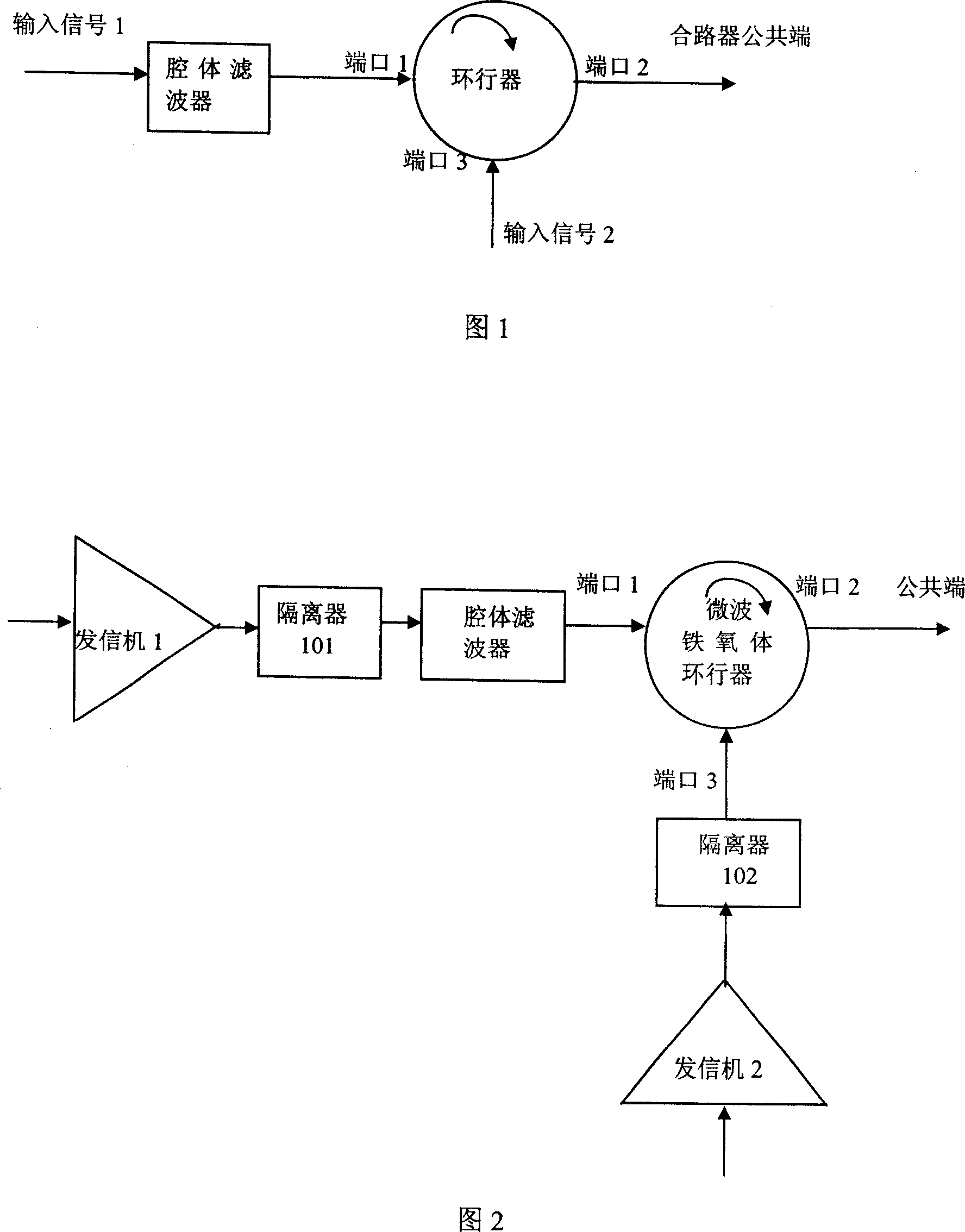
[0020] The implementation of the 2:1 low-loss combiner in the present invention is mainly composed of a filter and a circulator, wherein the electromagnetic wave energy circulating direction in the circulator is set as port 1 to port 2, port 2 to port 3, and the filter is connected to Port 1 of the circulator, filter and port 1 of the circulator together form the input port 1 of the combiner, port 2 of the circulator is the common output port of the combiner, and port 3 of the circulator constitutes the input port 2 of the combiner.

[0021] The low-loss combiner of the present invention realizes isolation and power synthesis between two transmitter paths through a high-power microwave circulator and a corresponding filter, and the insertion loss of the filter and the circulator is relatively small, The loss of the overall combiner can be controlled in a small range, and the 2-way transmitter can be isolated at the same time.

[0022] In the present invention, the filter is in...


PUM

PropertyMeasurementUnit
Isolationaaaaaaaaaa

Abstract

This invention discloses a low loss 2:1 path synthesizer including a cavity filter and a microwave ring device, in which. the energy circulation direction of the electromagnetic waves in the microwave ring device is set frpm port 1 to 2, and port 2 to port 3, said cavity filter is connected with port 1 of the ring device, and the cavity filter and port 1 of the microwave ring device make up of the input of the synthesizer, port 2 of the rign device is the public output port of the synthesizer and port 3 of the ring device constitutes input 2 of the synthesizer, since only the cavity filter is processed mechanically, it is simple for its mechanical process and debugging and the volume is reduced too.

Description

technical field [0001] The invention relates to a radio frequency microwave low-loss power synthesizing device, in particular to the realization of a 2:1 combiner in a wireless communication base station. Background technique [0002] RF microwave combiners are widely used in BTS (Base TransceiverStatiaon, base transceiver systems) in the field of modern wireless communications, because these products allow the different transmission functions of the BTS to be connected to a common antenna. This feature is important given the added cost, especially the aesthetics and potential zoning issues caused by adding another antenna to each section of the tower. In a BTS system, a low-loss combiner is an essential component. [0003] The commonly used RF microwave combiners generally have two structures. The first type of combiner is a solution based on a hybrid 3-dB bridge, in which the frequency interval between carriers can be very small, or even the same frequency can be achieved...

Claims


Application Information

Patent Timeline
IPC IPC(8): H01P1/207H01P1/38
Inventor 余敏德刘建利陈化璋
Owner ZTE CORP
Why Eureka
Try Eureka