High-homogenized ultra-thin LCD backlight device

A liquid crystal display and backlight device technology, applied in optics, instruments, nonlinear optics, etc., can solve the problems of uneven output light, sensors cannot detect data, obstruct light, etc., to reduce costs, avoid loss of luminous flux, The effect of increasing brightness

Inactive Publication Date: 2007-07-04
DYNASCAN TECH
View PDF0 Cites 2 Cited by
  • Summary
  • Abstract
  • Description
  • Claims
  • Application Information

AI Technical Summary

Problems solved by technology

Therefore, another disadvantage of the direct-illuminated backlight device using LED as the light source is that in order to avoid hindering the output light, the sensors are generally arranged around the backlight device.
Since it is not located on the path of the output light, coupled with the unevenness of the output light, the sensor cannot detect accurate data

Method used


Image

  • High-homogenized ultra-thin LCD backlight device
  • High-homogenized ultra-thin LCD backlight device
  • High-homogenized ultra-thin LCD backlight device

Examples


Embodiment Construction

[0026] The present invention provides an LCD display backlight device using LED as a light source. The LCD display in the present invention includes LCD displays for computers, LCD TVs, or other similar display devices that require backlighting.

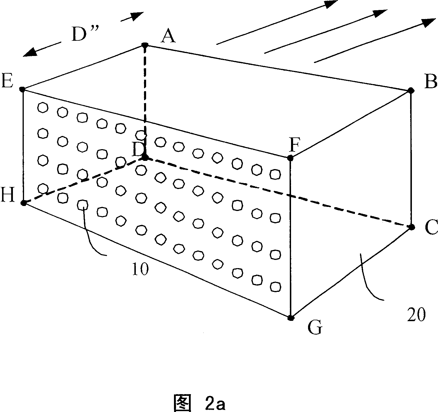
[0027] FIG. 2a is a schematic diagram of a backlight device according to a first embodiment of the present invention. As shown in FIG. 2a, the present invention at least includes a plurality of LEDs 10 as light sources, and a uniform cavity 20 disposed between the LEDs 10 and the back of an LCD panel (not shown). Please note that the LED 10 can be all white LEDs; or include red, blue, and green LEDs; or partially white, partially red, blue, and green; or any other suitable color. combination. The arrangement can be arranged in a matrix with regular intervals; or a group of several LEDs (such as a red light, a blue light, and two green LEDs), and the groups are arranged in a regular matrix; or is any other suitable arrangement. In ...


PUM


Abstract

The invention provides a LCD backlight device that includes several LED as the light source, and a uniform cavity mounted between the LED and the back of LED. The ray emitted from the LED are mixed and homogenized via several reflections to form a homogenizing front lighting, and it can omit the diffusing lens and the prismatic lens to reduce the cost and avoid the loss of luminous flux. The backlight device can reduce the thickness at the lowest and not need sacrifice the cost, heat dispersion and power, the service time, the whole homogenization of surface light is not affected by the difference of brightness,the chroma of special LED, and the fault.

Description

technical field [0001] The invention relates to the field of liquid crystal display backlight devices, in particular to a liquid crystal display backlight device using light-emitting diodes as light sources. Background technique [0002] Common liquid crystal display (LCD) or LCD TV backlight device (or backlight module, backlight module) mostly uses cold cathode fluorescent tube (Cold Cathode Fluorescent Lamp, CCFL) or light emitting diode (light emitting diode, LED) as light source, with side light The method enters from the side of the light guide plate of the backlight device, and the incident light is guided out from the light emitting surface of the light guide plate by the diffusion dot laid inside the light guide plate. Since the light emitting angle is very large, it is still One or more diffusion plates and prism plates must be used to homogenize and concentrate the angles to increase brightness and uniformity. [0003] As the size of the LCD increases, the above-...

Claims


Application Information

Patent Timeline
Patent Type & Authority Applications(China)
IPC IPC(8): G02F1/13357H01L33/00G02F1/1335
Inventor 王遵义
Owner DYNASCAN TECH
Why Eureka
Try Eureka