
Method for combusting a liquid fuel with staged atomisation

A liquid fuel, combustion method technology, applied in burners, lighting and heating equipment, etc., can solve problems such as irregular combustion and flame stability, and achieve the effects of reducing NOx formation, reducing NOx compound emissions, and uniform flame temperature

Inactive Publication Date: 2007-07-11
LAIR LIQUIDE SA POUR LETUDE & LEXPLOITATION DES PROCEDES GEORGES CLAUDE
View PDF1 Cites 1 Cited by
  • Summary
  • Abstract
  • Description
  • Claims
  • Application Information

AI Technical Summary

Problems solved by technology

This leads to irregular combustion and flame stability issues

Method used


Image

  • Method for combusting a liquid fuel with staged atomisation
  • Method for combusting a liquid fuel with staged atomisation
  • Method for combusting a liquid fuel with staged atomisation

Examples


Embodiment Construction

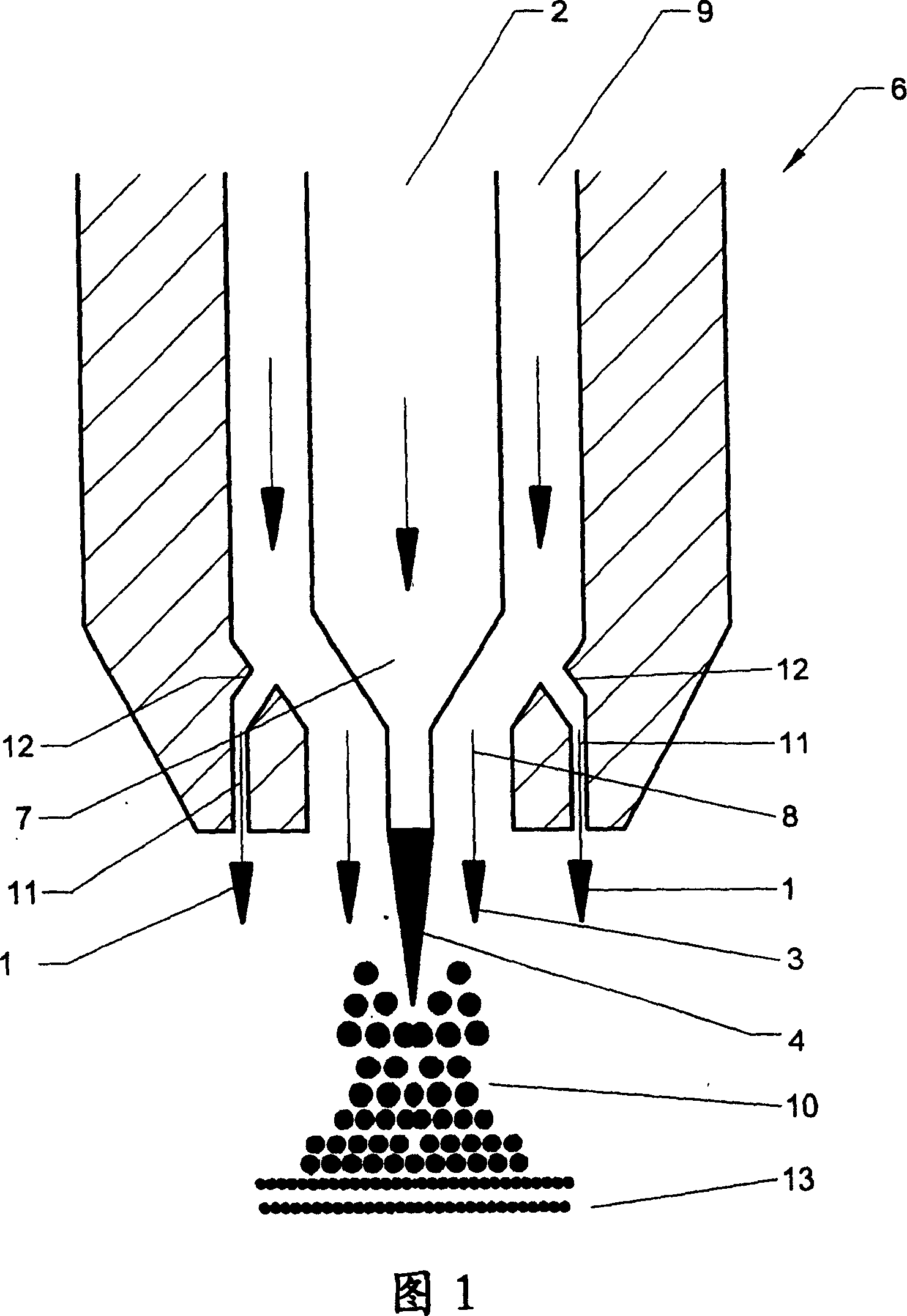
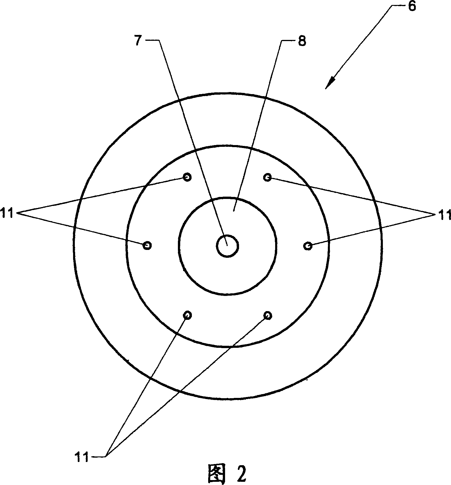
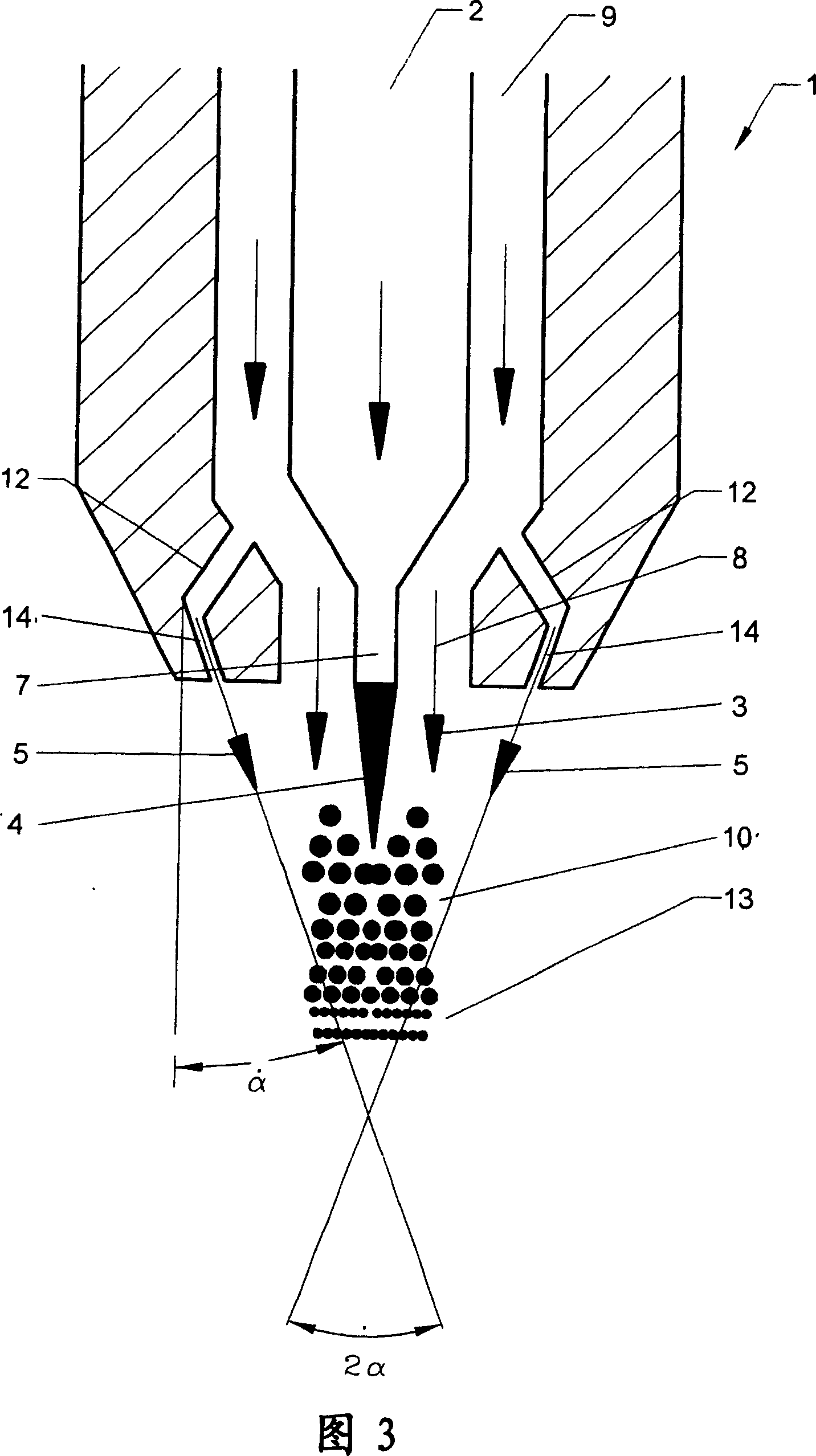
[0032]As shown in FIGS. 1 and 2, the combustion method according to the invention is carried out by means of a burner comprising a jet-guided atomizing head 6 utilizing external mixing. The atomizing head 6 includes:

[0033] - an injection line 7 for the flow of liquid fuel 4 delivered by the fuel supplier 2; and

[0034] - an atomizing gas injection line 8 concentric with the fuel injection line 7 and connected to the atomizing gas supply 9 and terminating in contact with the fuel flow 4 so as to be in contact with the main atomizing gas flow 3 produces liquid fuel spray 10 under the action.

[0035] Furthermore, the atomizing head 6 has six secondary injection channels 11 aligned parallel to the fuel injection line 7 and the atomizing gas injection line 8 . These six secondary spray channels 11 are evenly distributed around the spray lines 7 , 8 and are designed to generate a secondary atomizing gas flow 1 that flows out of the atomizing gas supply 9 via a bypass channel ...


PUM


Abstract

The method involves producing a liquid fuel sprayby injecting a main flow (3) of an atomization gas such as air in contact with a liquid fuel flow (4). A flow of the atomization gas is injected near the spray so as to form a secondary atomization of the spray before the spray is in contact with a jet of oxidant in order to process fuel combustion. An independent claim is also included for a burner comprising a liquid fuel injection unit.

Description

technical field [0001] The invention relates to a liquid fuel combustion method and a burner for implementing the method. Background technique [0002] For example, in installing a combustion system for an industrial furnace, a major concern is to optimize combustion efficiency by optimally controlling flame characteristics while meeting the heat transfer requirements of the heating method and minimizing air pollutant emissions. [0003] Two-phase combustion of liquid fuels with oxidizing gases involves two main steps before actual combustion takes place. In the first step, it is necessary to atomize the liquid fuel with the sprayed atomizing gas in order to destabilize the liquid fuel flow and form a fuel spray with a large contact surface area with the oxidant to promote combustion. The atomizing gas used may be, for example, air, oxygen, steam or even natural gas. The liquid fuel droplets thus formed then need to evaporate before the fuel can be combusted with the oxidi...

Claims


Application Information

Patent Timeline
IPC IPC(8): F23D11/00
CPCF23D11/108
Inventor B·勒鲁P·J-M·勒库特M·阿米拉特G·康斯坦丁R·P·特斯阿瓦
Owner LAIR LIQUIDE SA POUR LETUDE & LEXPLOITATION DES PROCEDES GEORGES CLAUDE
Learn More