Membrane switch and method of manufacturing the same

a technology of membrane switches and manufacturing methods, applied in the field of electromechanical switches, can solve the problems of low product defect-free rate, poor close adaptation, and unfavorable product quality, and achieve the effects of preventing liquid glue, reducing production costs, and reducing production costs

Active Publication Date: 2018-06-19
KUNSHAN JOING TECH
View PDF12 Cites 0 Cited by
  • Summary
  • Abstract
  • Description
  • Claims
  • Application Information

AI Technical Summary

Benefits of technology

[0005]The present invention is intended to overcome the deficiencies of the prior art and provide a membrane switch with simple structure, low cost and in which the adhesive layer does not affect the contact between the upper and lower conductive dots, and a method of manufacturing the same.
[0016]Due to the use of the above technical solution, the present invention has the following advantages when compared with the prior art: by coating the glue on the upper and lower surfaces of the isolation layer and thereby bonding with the upper membrane and the lower membrane, the membrane switch according to the present invention can effectively overcome defects such as bubbles, bulges, lack of glue and the like caused by the conventional printing process, prevent liquid glue from lose efficacy and simplify the membrane-switch production process; and the glue on the upper and / or lower surfaces of the isolation layer employing hot-melt glue may increase the degree of automation and reduce human costs.

Problems solved by technology

However, the following problems are prone to occur in screen printing: uneven adhesive, poor close adaptation, and low product defect-free rate; the double-sided adhesive tape is easily deformed after punching and forming, easily wrinkles and is difficult for operation when bonding, and the membrane switch manufactured has poor waterproof and sealing performance and is easy to be oxidized and corroded, and thus resulting in the instability of the membrane switch.
Although this manufacturing method of a membrane switch is simple, practical and easy to operate, there is no glue to be printed on the UV pad layer is very difficult to achieve, due to that it is very apt to print the glue on the conductive layers after the upper membrane is printed with the glue and bonded with the UV pad layer, and then affect the contact between the upper and lower conductive layers.
In addition, printing of the glue is likely to cause defects such as bubbles and hollow resulting in the membrane switch has quality problems.

Method used


Image

  • Membrane switch and method of manufacturing the same
  • Membrane switch and method of manufacturing the same

Examples


embodiment 1

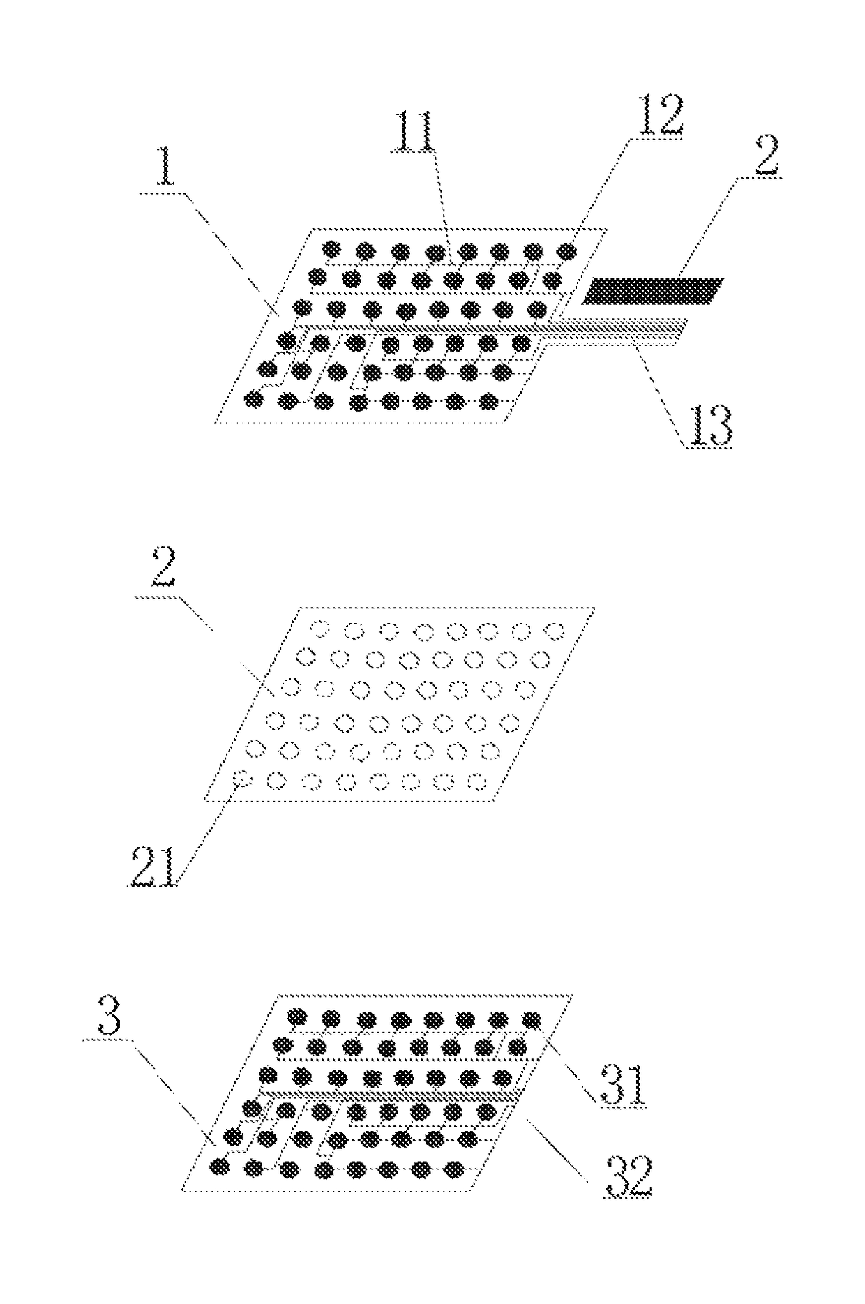
[0020]The membrane switch shown in FIG. 1 mainly includes an upper membrane 1, an isolation layer 2 and a lower membrane 3, the isolation layer 2 being located between the upper membrane 1 and lower membrane 2. Two opposite surfaces of the upper membrane 1 and the lower membrane 3 (that is, the undersurface of the upper membrane 1 and the top surface of the lower membrane 3) are respectively printed with upper conductive dots 11 and upper conductive traces 12 connecting the upper conductive dots 11 as well as lower conductive dots 31 and conductive traces 32, positions of the upper conductive dots 11 and the lower conductive dots 31, and the positions of the upper conductive traces 12 and the lower conductive traces 32 match up with and correspond to each other. Holes 21 are provided in the isolation layer 2 at the positions corresponding to the upper conductive dots 11 and the lower conductive dots 31. Glue is coated on the upper and lower surfaces of the isolation layer 2 to bond ...

embodiment 2

[0022]The present embodiment provides a method of manufacturing a membrane switch, including the following steps:

[0023](a) coating the upper surface and / or lower surface of the isolation layer exclusive of the positions of the holes with glue;

[0024](b) bonding and adhering the sides of the upper membrane and the lower membrane printed with the conductive dots and traces respectively to the upper surface and the lower surface of the isolation layer via glue, making the positions of the conductive dots corresponding to each other, and forming a membrane switch by bonding upper membrane and lower membrane both on the isolation layer via glue.

[0025]In this embodiment, the specific steps of the method of manufacturing a membrane switch have a great degree of freedom. One surface of the isolation layer may firstly be coated with glue and bonded with one of the upper membrane and lower membrane, and then the other surface of the isolation layer is coated with glue and bonded to the other o...


PUM


Abstract

A membrane switch and a method of manufacturing the same, includes upper and lower membranes printed with upper and lower conductive dots and an isolation layer between them, holes being opened in the isolation layer corresponding to the dots, the isolation layer is bonded with the upper and lower membranes respectively via the glue coated on the upper surface and the lower surface thereof; and the glue may employ hot melt glue. This method of manufacturing the membrane switch includes a coating the upper surface and / or lower surface of the isolation layer exclusive of the positions of the holes with glue; bonding and adhering the sides of the upper membrane and the lower membrane printed with the conductive dots and respectively to the upper surface and the lower surface of the isolation layer via glue, making the positions of the conductive dots and the holes corresponding to each other.

Description

TECHNICAL FIELD[0001]The present invention relates to the field of electronic switches, in particular to a manufacturing method of membrane switches for computer keyboards, keyboards of communications equipment and keyboards of household appliances, etc.BACKGROUND OF INVENTION[0002]With the continuous development of science and technology, varieties of electronic equipment have emerged in abundance. Keyboards are common devices of many electronic equipment, for inputting text information, etc., and commonly are computer keyboards, keyboards of communications equipment and keyboards of household appliances, etc. A membrane switch is a component of the aforesaid keyboards, the development of which now tends towards thin and tight designs, flexibility and low cost and which with advantages such as small size, light weight, simple to operation, etc. Membrane switches have been widely used in various products, for example intelligent electronic instruments, medical instruments, numerical...

Claims


Application Information

Patent Timeline
Patent Type & Authority Patents(United States)
IPC IPC(8): H01H1/10H01H13/704H01H13/88
CPCH01H13/704H01H13/88H01H2227/008H01H2229/028H01H2229/056H01H2239/056
Inventor WANG, YUQIU, ZEAN
Owner KUNSHAN JOING TECH
Why Eureka
Try Eureka