
Rendering tool information as graphic overlays on displayed images of tools

a tool information and graphic overlay technology, applied in the field of robotic systems, can solve problems such as difficult to readily see, objectionable obstructing the image of tools and/or objects, and difficult to understand the information of tools

Active Publication Date: 2018-06-26
INTUITIVE SURGICAL OPERATIONS INC
View PDF505 Cites 59 Cited by
  • Summary
  • Abstract
  • Description
  • Claims
  • Application Information

AI Technical Summary

Benefits of technology

The present invention is a robotic system that displays tool information on a display in a way that is easily associated with the image of the tool being viewed. This allows users to easily identify the tool being used without having to refocus their eyes on the display. Additionally, the system provides three-dimensional tool information on a stereo display, without requiring users to do so. These technical effects improve the usability and efficiency of the robotic system.

Problems solved by technology

However, such positioning of the tool information may objectionably obstruct images of the tools and / or objects upon which the tools are performing a procedure at the time.
Also, when the end effectors of two or more tools are in close proximity to one another, it may not be readily apparent which tool the tool information pertains to at the time.
This may be especially problematic if the tool information is stationary and the end effectors are moving.
When the tool information is provided outside the gaze area of the operator, however, it may be distracting for the operator to visually find and / or associate the provided tool information with its corresponding tool because the operator's eyes must shift from the area in which the operator is currently gazing to another area on the display.
In the case of a stereo display, the situation becomes even more complicated, because the operator's eyes not only have to shift vertically and horizontally around the display to find the tool information, they may also have to look for and focus on tool information at a different depth than the three-dimensional images of the object and tools that the operator is viewing at the time on a stereo vision display.

Method used


Image

  • Rendering tool information as graphic overlays on displayed images of tools
  • Rendering tool information as graphic overlays on displayed images of tools
  • Rendering tool information as graphic overlays on displayed images of tools

Examples


Embodiment Construction

[0019]Although a medical robotic system is described herein, it is to be appreciated that the various aspects of the invention are not to be limited to medical robotic systems. They are applicable to robotic systems in general.

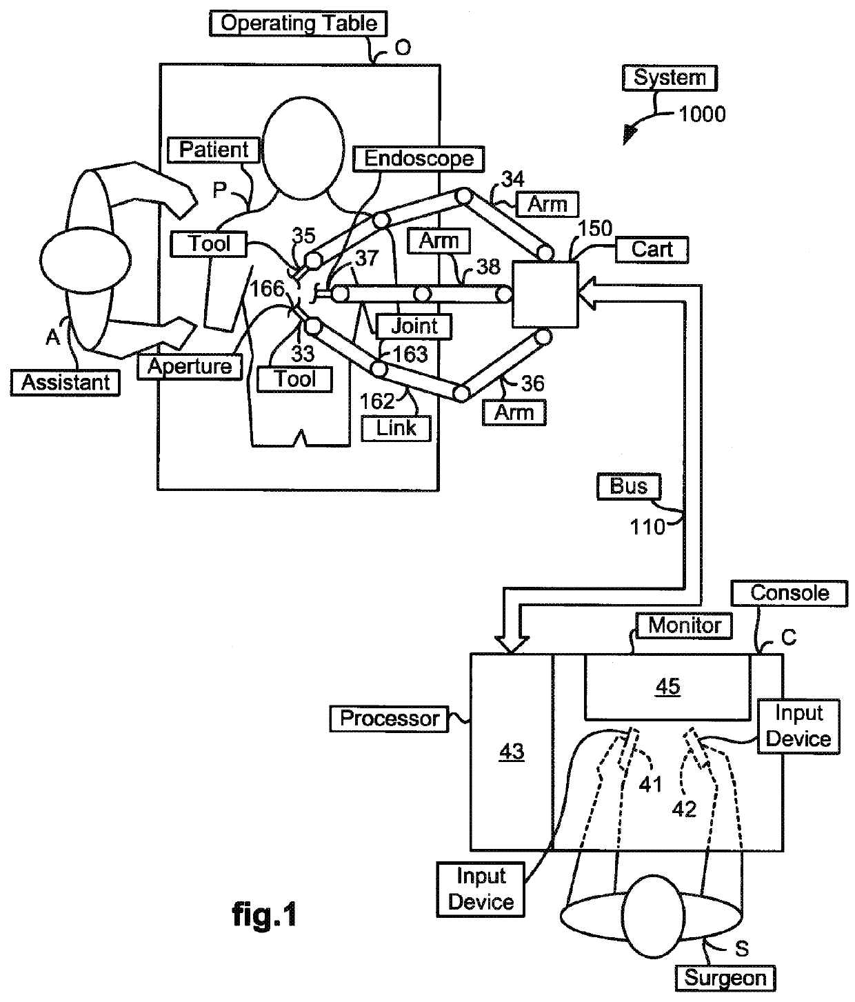
[0020]FIG. 1 illustrates a top view of an operating room in which a medical robotic system 1000 is being employed by a Surgeon (“S”) to perform a medical procedure on a Patient (“P”). The medical robotic system in this case is a Minimally Invasive Robotic Surgical (MIRS) system including a Console (“C”) utilized by the Surgeon while performing a minimally invasive diagnostic or surgical procedure on the Patient with assistance from one or more Assistants (“A”) while the Patient is on an Operating table (“O”).

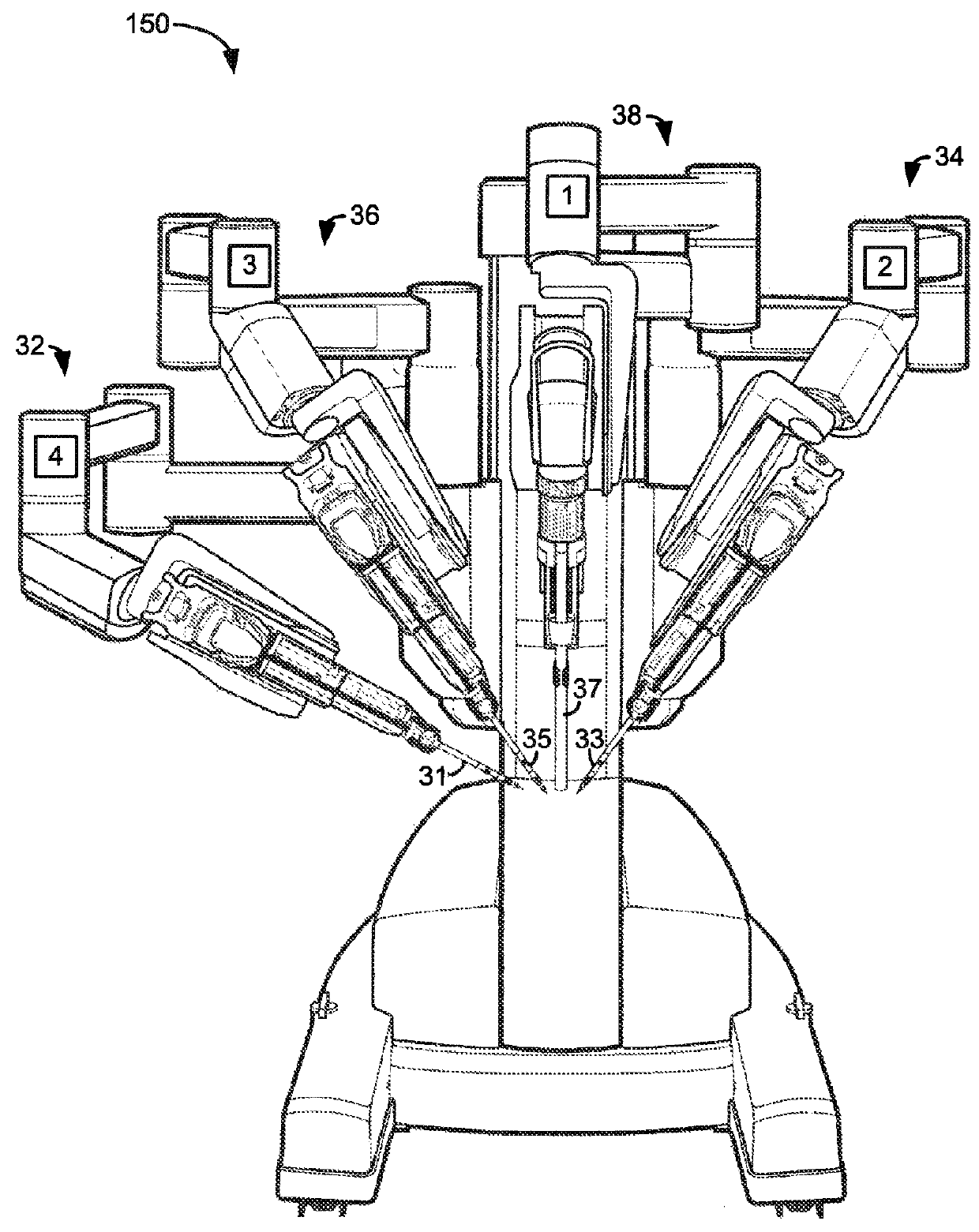
[0021]The Console, as further described in reference to FIG. 4, includes a processor 43 which communicates with a movable cart 150 over a bus 110. A plurality of robotic arms 34, 36, 38 are included on the cart 150. A tool 33 is held and manipulated by rob...


PUM


Abstract

An operator telerobotically controls tools to perform a procedure on an object at a work site while viewing real-time images of the work site on a display. Tool information is provided in the operator's current gaze area on the display by rendering the tool information over the tool so as not to obscure objects being worked on at the time by the tool nor to require eyes of the user to refocus when looking at the tool information and the image of the tool on a stereo viewer.

Description

CROSS REFERENCE TO RELATED APPLICATIONS[0001]This application is a continuation-in-part of U.S. application Ser. No. 12 / 415,354 filed Mar. 31, 2009, which is incorporated herein by reference; and U.S. application Ser. No. 12 / 415,354 is a continuation-in-part of U.S. application Ser. No. 11 / 478,531, filed Jun. 29, 2006, and a continuation-in-part of U.S. application Ser. No. 12 / 163,087, filed Jun. 27, 2008.FIELD OF THE INVENTION[0002]The present invention generally relates to robotic systems and in particular, to a robotic system, and a method implemented therein, for rendering tool information as graphic overlays on displayed images of tools.BACKGROUND OF THE INVENTION[0003]In a robotic system, one or more tools may be telerobotically controlled by an operator to perform a procedure on an object at a work site. A camera is provided at the work site to capture images of end effectors of the tools as they interact with the object to perform the procedure, so that the operator may view...

Claims


Application Information

Patent Timeline
Patent Type & Authority Patents(United States)
IPC IPC(8): G06T11/60A61B90/00A61B34/30A61B34/37G05B19/42G06T11/40B25J9/16A61B34/20A61B34/00
CPCG06T11/60A61B34/37A61B90/36B25J9/1666B25J9/1671B25J9/1692G05B19/4202G06T11/40A61B34/30G05B2219/45123A61B34/20A61B34/25A61B90/361A61B2034/2061A61B2090/371G05B2219/36432G05B2219/39083G05B2219/39096G05B2219/39449G05B2219/40607G05B2219/45117Y02P90/02
Inventor ITKOWITZ, BRANDON D.HALABE, DANIEL J.ZHAO, TAODIMAIO, SIMON P.HASSER, CHRISTOPHER J.MOHR, CATHERINE J.MOHR, PAUL W.LARKIN, DAVID Q.HOFFMAN, BRIAN DAVIDZHAO, WENYI
Owner INTUITIVE SURGICAL OPERATIONS INC
Learn More