
Surface mountable sensor array fabric

a sensor array and surface mount technology, applied in the field of measuring instruments, can solve the problems of large radar and microphone arrays, no known device that provides these solutions, and expensive instruments

Inactive Publication Date: 2018-07-03
WAVE ARRAY SCI INC
View PDF2 Cites 1 Cited by
  • Summary
  • Abstract
  • Description
  • Claims
  • Application Information

AI Technical Summary

Benefits of technology

[0016]One or more embodiments may have an inner cladding layer located on the bottom side of the sheet, which is adjacent to the surface of the object to be measured. One or more embodiments may have an outer cladding layer located on the top side of the sheet. Cladding layers may for example protect components of the sheet from the environment. An inner cladding layer may provide material that attaches to or interfaces with the object to be measured.

Problems solved by technology

These radar and microphone arrays are typically large, expensive instruments that are installed into a site or an area.
There are no known devices that provide these solutions.

Method used


Image

  • Surface mountable sensor array fabric
  • Surface mountable sensor array fabric
  • Surface mountable sensor array fabric

Examples


Embodiment Construction

[0030]A surface mountable sensor array fabric will now be described. In the following exemplary description numerous specific details are set forth in order to provide a more thorough understanding of embodiments of the invention. It will be apparent, however, to an artisan of ordinary skill that the present invention may be practiced without incorporating all aspects of the specific details described herein. In other instances, specific features, quantities, or measurements well known to those of ordinary skill in the art have not been described in detail so as not to obscure the invention. Readers should note that although examples of the invention are set forth herein, the claims, and the full scope of any equivalents, are what define the metes and bounds of the invention.

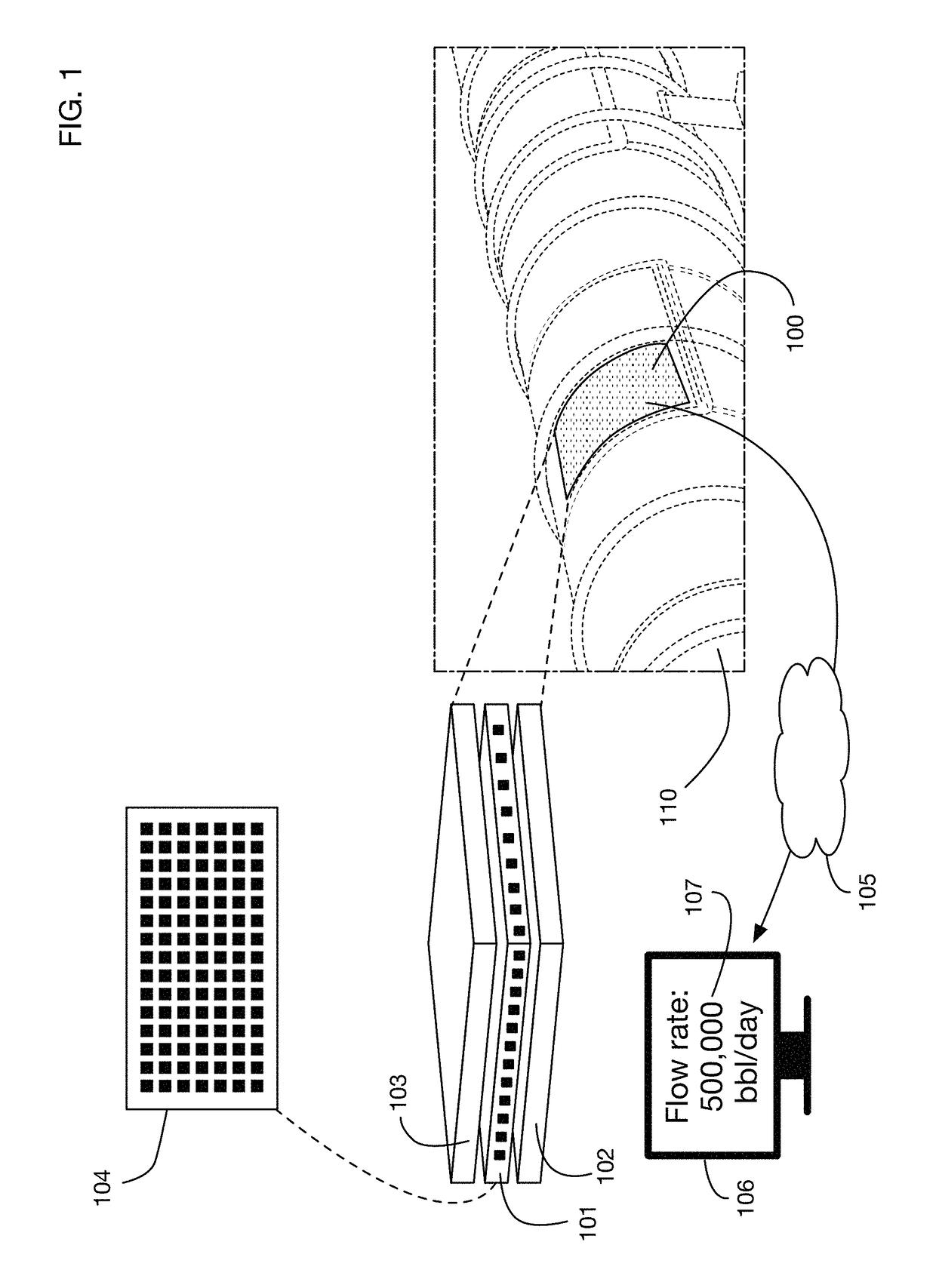
[0031]FIG. 1 shows an illustrative embodiment of the invention configured to be placed on the surface of a pipeline 110. One or more embodiments of the invention may be configured to be placed on, near, or in th...


PUM


Abstract

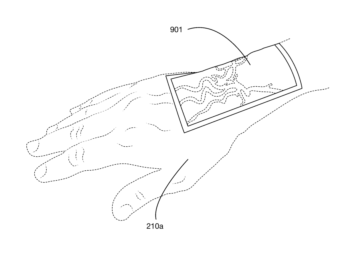
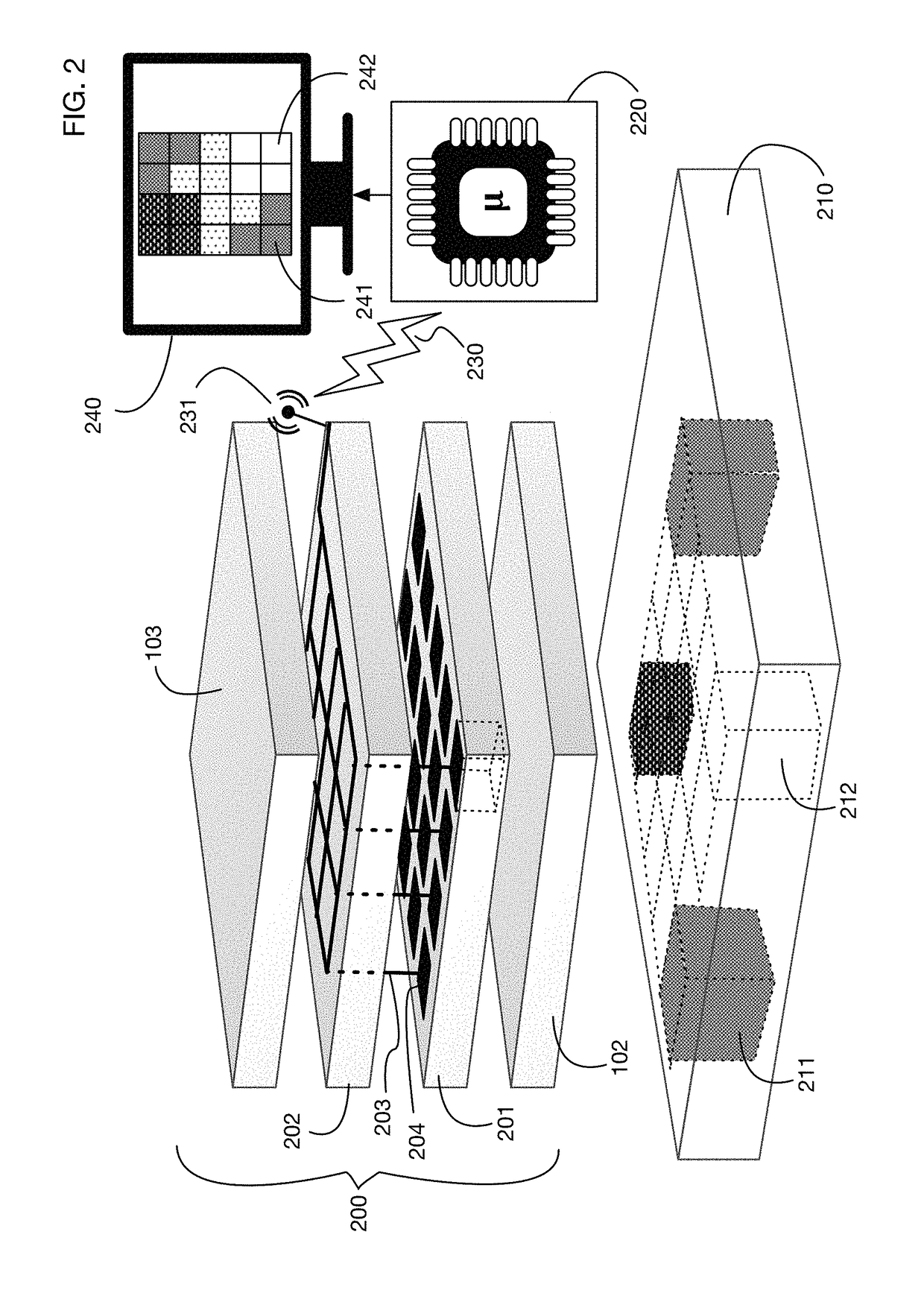
A fabric with an integrated sensor array and optionally with an integrated display; the fabric may be mounted to the surface of an object to be measured or monitored. The fabric may comprise multiple laminar layers, such as sensor layers, processing layers, display layers, and cladding layers for protection and sealing. Data analysis performed by processing layers may include beamforming operations, frequency filters, or any desired transformations. An illustrative display uses a layer of liquid crystal cells sandwiched between polarizing filter layers. An illustrative sensor array is an array of piezoelectric acoustic sensors formed by adjacent layers of calcium carbonate cells and potassium bitartrate cells. An application of acoustic sensor arrays may include for example a patch attached to a person's skin that senses and displays the location and size of blood vessels under the skin using the sound generated by blood flow.

Description

BACKGROUND OF THE INVENTION[0001]Field of the Invention[0002]One or more embodiments of the invention are related to the field of measuring instruments. More particularly, but not by way of limitation, one or more embodiments of the invention enable a sensor array integrated into a fabric that may be attached to or placed near an object to be measured. The fabric may include integrated data analysis capabilities and an integrated display.[0003]Description of the Related Art[0004]Sensor arrays are known in the art. For example, phased array radar systems are in widespread use. Microphone arrays for reception and processing of acoustic signals are also known. An array of sensors provides several potential advantages over individual sensors, including for example improved directionality of signal reception. These radar and microphone arrays are typically large, expensive instruments that are installed into a site or an area.[0005]Sensors that can be attached to a surface of an object a...

Claims


Application Information

Patent Timeline
Patent Type & Authority Patents(United States)
IPC IPC(8): A61B8/00A61B5/026A61B7/00A61B5/00A61B8/13A61B8/08
CPCA61B5/026A61B5/489A61B5/6825A61B5/6833A61B5/7225A61B7/00A61B8/00A61B5/0004A61B2562/046A61B5/742A61B8/08A61B8/13A61B8/4281A61B8/483A61B5/6801A61B7/02
Inventor PASSMORE, CHARLES GREGORY
Owner WAVE ARRAY SCI INC
Learn More