Antenna device, wireless communication apparatus, and radar apparatus

a technology of wireless communication and antenna device, which is applied in the direction of antenna earthing, individually energised antenna array, instruments, etc., can solve the problems of increasing the size of the antenna device, increasing the cost, and the difficulty of conventional ebg structure in ensuring sufficient high isolation across a wide frequency bandwidth, so as to achieve high isolation and wide frequency bandwidth

Inactive Publication Date: 2018-07-03
PANASONIC INTELLECTUAL PROPERTY MANAGEMENT CO LTD
View PDF14 Cites 9 Cited by
  • Summary
  • Abstract
  • Description
  • Claims
  • Application Information

AI Technical Summary

Benefits of technology

[0007]One non-limiting and exemplary embodiment provides an antenna device including an EBG structure and being capable of ensuring high isolation across a wide frequency bandwidth.
[0010]An antenna device including an EBG structure according to one general aspect of the present disclosure can ensure high isolation across a wide frequency bandwidth.

Problems solved by technology

Therefore, the conventional EBG structure has difficulty in ensuring sufficiently high isolation across a wide frequency bandwidth.
Meanwhile, providing an additional component or the like to change the antiresonant frequency of the EBG structure causes an increase in size of the antenna device and also causes an increase in cost.

Method used


Image

  • Antenna device, wireless communication apparatus, and radar apparatus
  • Antenna device, wireless communication apparatus, and radar apparatus
  • Antenna device, wireless communication apparatus, and radar apparatus

Examples


first embodiment

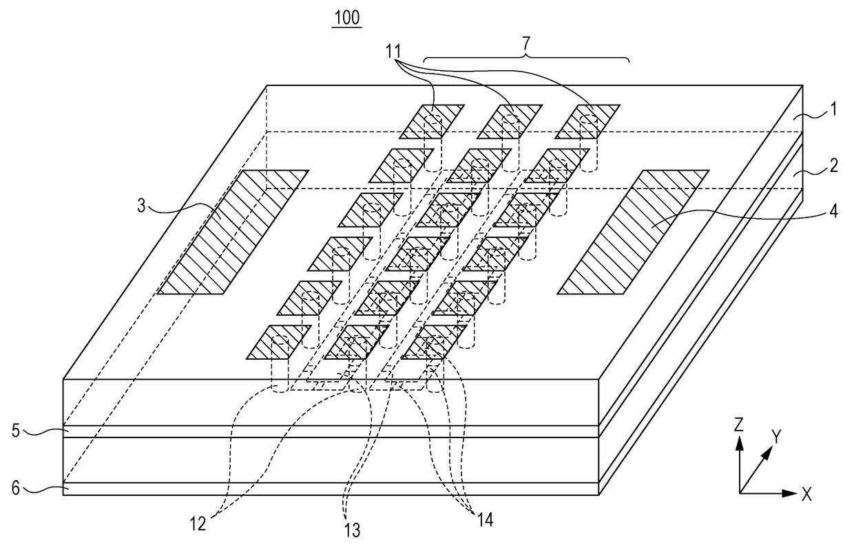
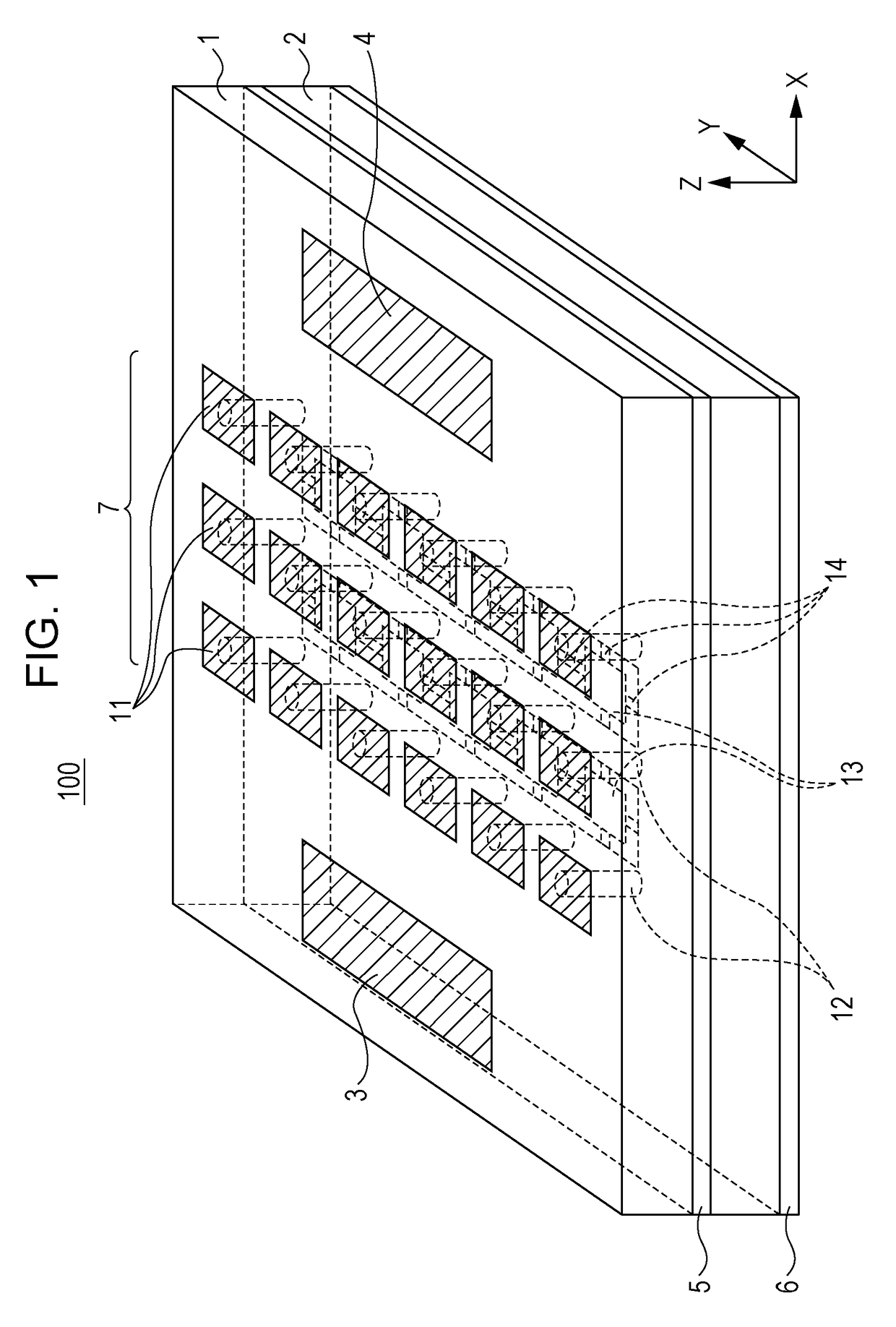
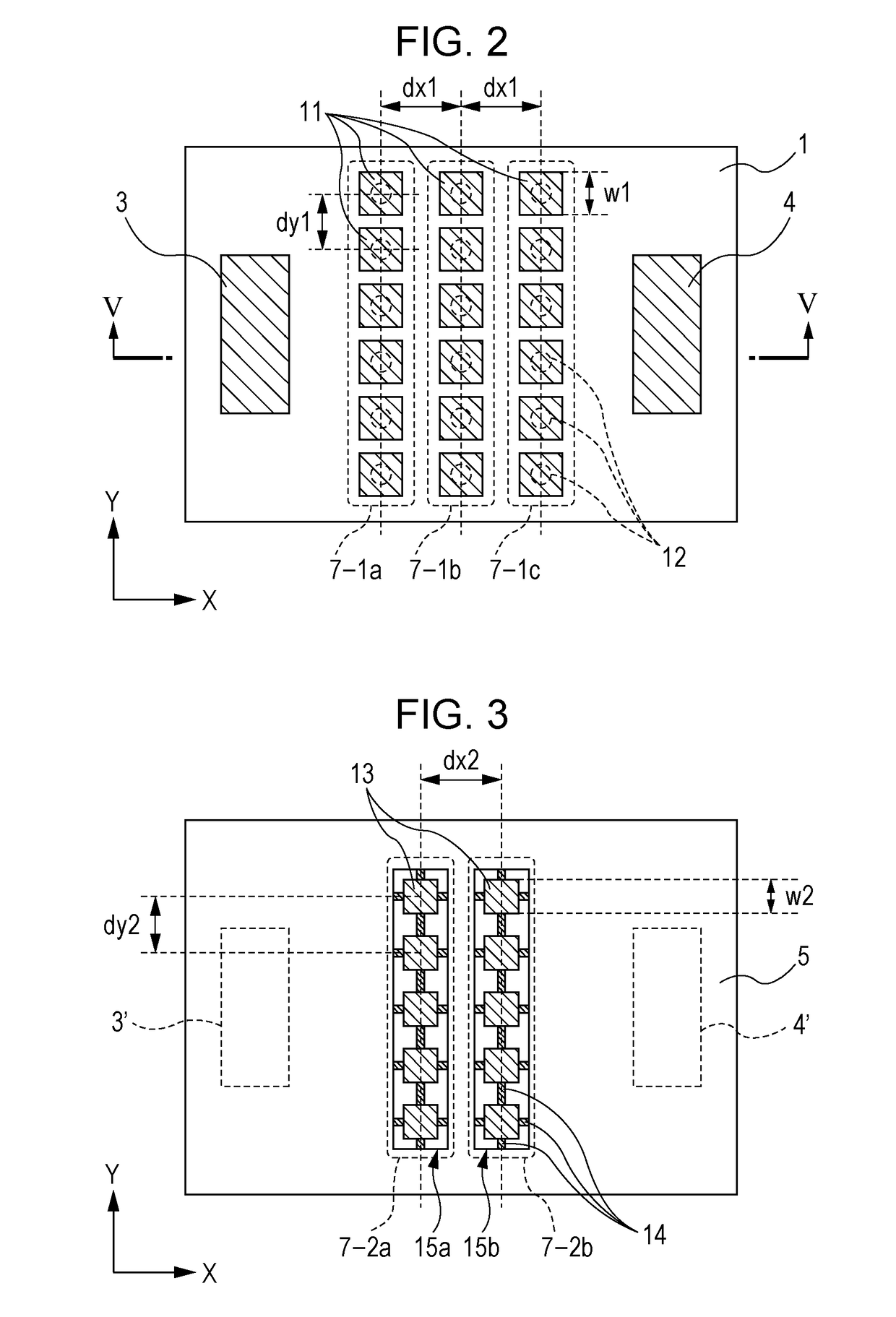
[0029]FIG. 1 is a perspective view showing an antenna device 100 according to a first embodiment. FIG. 2 is a top view showing a first conductor layer of the antenna device 100 shown in FIG. 1. FIG. 3 is a top view showing a second conductor layer of the antenna device 100 shown in FIG. 1, FIG. 4 is a top view showing a third conductor layer of the antenna device 100 shown in FIG. 1. FIG. 5 is a cross-sectional view of the antenna device 100 as taken along the line V-V in FIG. 2.

[0030]The antenna device 100 includes a substrate. The substrate includes dielectric layers 1 and 2, a first conductor layer provided on an upper surface of the dielectric layer 1, a second conductor layer provided between the dielectric layers 1 and 2, and a third conductor layer provided on a lower surface of the dielectric layer 2. In other words, the first and second conductor layers are provided on both surfaces, respectively, of the first dielectric layer 1, and the third conductor layer is provided on...

second embodiment

[0060]FIG. 15 is a block diagram showing a wireless communication apparatus according to a second embodiment. The wireless communication apparatus shown in FIG. 15 includes an antenna device 100 shown in FIG. 1, a wireless communication circuit 111, and a signal processing circuit 112. The wireless communication circuit 111 emits from the antenna device 100 a radio signal produced by modulating a baseband signal sent from the signal processing circuit, and sends to the signal processing circuit 112 a baseband signal produced by demodulating a radio signal received by the antenna device 100.

third embodiment

[0061]FIG. 16 is a block diagram showing a radar apparatus according to a third embodiment. The radar apparatus shown in FIG. 16 includes an antenna device 100 shown in FIG. 1, a radar transmitting and receiving circuit 121, a signal processing circuit 122, and a display device 123. The radar transmitting and receiving circuit 121 radiates radar waves from the antenna device 100 under control of the signal processing circuit 122 and receives radar waves reflected by the target and entering the antenna device 100. The signal processing circuit 122 determines the distance from the antenna device 100 to the target and the speed of the target, for example, on the basis of the propagation time of and a change in frequency of radar waves, and displays the results on the display device 123.

[0062]An antenna device 100 according to each of the embodiments makes it possible to improve isolation and achieve a wide isolation band.

[0063]An antenna device, a wireless communication apparatus, and ...


PUM


Abstract

An antenna device of the present disclosure includes: a dielectric layer; first and second conductor layers provided on both surfaces, respectively, of the dielectric layer; first and second antenna elements provided in the first conductor layer; a grounded conductor provided in the second conductor layer; and an EBG structure provided between the first and second antenna elements, wherein the EBG structure includes a first EBG portion provided in the first conductor layer, the first EBG portion including a plurality of first patch conductors electromagnetically coupled to the grounded conductor, and a second EBG portion provided in the second conductor layer, the second EBG portion including a plurality of second patch conductors electromagnetically coupled to the grounded conductor.

Description

BACKGROUND[0001]1. Technical Field[0002]The present disclosure relates to an antenna device including a plurality of antenna elements and an EBG (electromagnetic band gap) structure. The present disclosure also relates to a wireless communication apparatus including such an antenna device and a radar apparatus including such an antenna device.[0003]2. Description of the Related Art[0004]Conventionally, it has been known that in an antenna device including a plurality of antenna elements and communicating in a millimeter-wave band, an EBG structure is used to ensure isolation between the antenna elements (see Japanese Patents Nos. 4650302, 5112204, and 5212949) Since the EBG structure becomes higher in impedance at a predetermined frequency (antiresonant frequency), the antenna device including the EBG structure can enhance the isolation between the antenna elements at the frequency.[0005]A known example of the EBG structure is one that includes mushroom conductors including a plural...

Claims


Application Information

Patent Timeline
Patent Type & Authority Patents(United States)
IPC IPC(8): H01Q1/52H01Q1/24H01Q1/48H01Q1/38H01Q15/00H01Q21/06
CPCH01Q1/38H01Q1/243H01Q1/48H01Q1/525H01Q15/008H01Q1/521H01Q21/06G01S7/006H01Q1/50
Inventor TAGI, HIROYOSHIIWAKI, HIDEKI
Owner PANASONIC INTELLECTUAL PROPERTY MANAGEMENT CO LTD
Why Eureka
Try Eureka