Flow meter for use with a ventilator

a flow meter and ventilator technology, applied in the field of flow sensors, can solve the problems of pharmacologic therapy that has in general proved disappointing in treating certain breathing disorders, affecting the measurement accuracy of flow meters, and affecting the patient's breathing, so as to improve the measurement accuracy and reduce the resistance of air flow

Active Publication Date: 2018-07-10
BREAS MEDICAL
View PDF9 Cites 2 Cited by
  • Summary
  • Abstract
  • Description
  • Claims
  • Application Information

AI Technical Summary

Benefits of technology

[0010]One aim of the present disclosure is to improve the measurement accuracy of a flow meter. A flow meter with a low air flow resistance is presented.

Problems solved by technology

Surgical techniques to remedy breathing disorders constitute a considerable risk for the patient and can lead to permanent injury or even mortality.
Pharmacologic therapy has in general proved disappointing with respect to treating certain breathing disorders, e.g. sleep apnea.
Ventilatory failure includes all forms of insufficient ventilation with respect to metabolic need whether occurring during wake or periods of sleep.
Ventilatory failure is a potentially life threatening condition.
The general comorbidity in patients with failing ventilation is considerable.
The condition is highly disabling in terms of reduced physical capacity, cognitive dysfunction in severe cases and poor quality of life.
Patients with ventilatory failure therefore experience significant daytime symptoms but in addition, the majority of these cases experience a general worsening of their condition during state changes such as sleep.
Daytime complications include sleepiness and cognitive dysfunction.
Not only may CPAP be uncomfortable for the patient due to a sensed increased work of breathing during ventilation, specifically expiration.
Some forms of apnea, mainly including those of central origin, and most forms of hypoventilation are only poorly controlled by CPAP.
A system that does not comply with patient efforts creates an air trapping situation and increase discomfort for the patient as well as considerably increasing the possibility of anxiety for the patient.
A too low Shore hardness value will increase the tendency of the membrane to stick or cling to adjacent surfaces thereby obstructing the response of the membrane to pressure variations there over.
A too high Shore hardness value, on the other hand, may lead to a slow response to pressure variations due to the resulting stiffness of the membrane.

Method used


Image

  • Flow meter for use with a ventilator
  • Flow meter for use with a ventilator
  • Flow meter for use with a ventilator

Examples


Embodiment Construction

[0064]In the following description, for purposes of explanation and not limitation, specific details are set forth, such as particular components, elements, techniques, etc. in order to provide a thorough understanding of the example embodiments. However, it will be apparent to one skilled in the art that the example embodiments may be practiced in other manners that depart from these specific details. In other instances, detailed descriptions of well-known methods and elements are omitted so as not to obscure the description of the example embodiments. The terminology used herein is for the purpose of describing the example embodiments and is not intended to limit the embodiments presented herein.

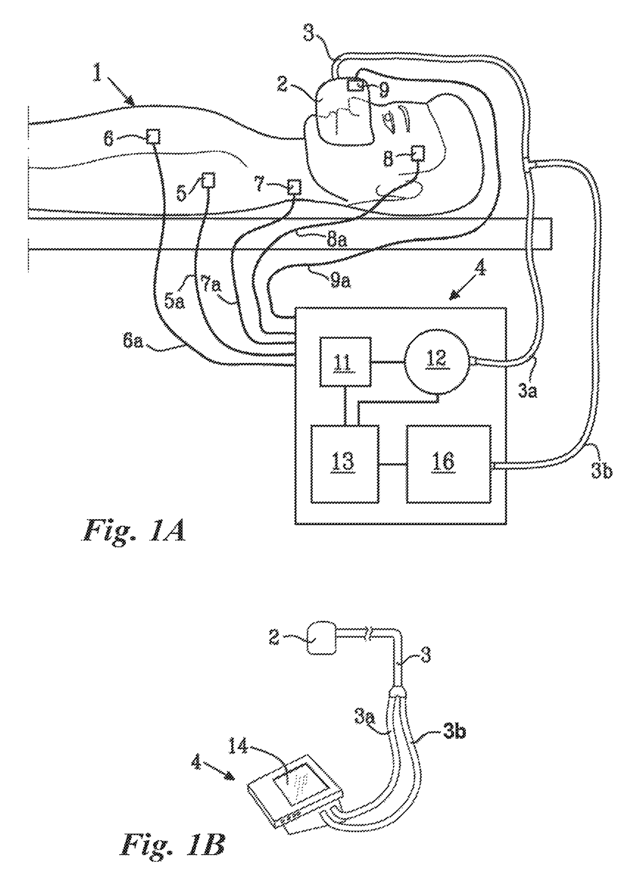
[0065]In FIGS. 1A and 1B a mechanical ventilation system used for the treatment of hypoventilation disorders is illustrated schematically. A ventilation system may comprise a mechanical ventilator 4 supplying pressurized breathing gas, tubing 3 for guiding breathing gas to and from the pat...


PUM


Abstract

A turbulator adapted to be mounted to or inserted in an inlet portion of a flow meter for a ventilator is disclosed. The turbulator is adapted to create a turbulent gas flow in the inlet portion downstream of the turbulator upon passage of a gas flow therethrough. A flow meter for a ventilator is provided. The flow meter may comprise such turbulator. The turbulator may be arranged in the inlet portion of the flow meter. A membrane for a ventilator flow meter is provided, as well as a flow meter comprising the membrane. A flow meter comprising a turbulator and a membrane is disclosed.

Description

TECHNICAL FIELD[0001]The present invention relates to a flow sensor. In particular, it relates to a flow sensor for a mechanical ventilator.BACKGROUND OF THE INVENTION[0002]Patients suffering from different forms of breathing disorders can be subject to several types of treatments depending on the illness or disorder present. Such treatments include surgical procedures, pharmacologic therapy, and non-invasive mechanical techniques. Surgical techniques to remedy breathing disorders constitute a considerable risk for the patient and can lead to permanent injury or even mortality. Pharmacologic therapy has in general proved disappointing with respect to treating certain breathing disorders, e.g. sleep apnea. It is therefore of interest to find other treatments, preferably non-invasive techniques.[0003]A mechanical ventilator represents a non-invasive technique for treatment of certain breathing disorders such as ventilatory failure, hypoventilation, and periodic breathing during sleep ...

Claims


Application Information

Patent Timeline
Patent Type & Authority Patents(United States)
IPC IPC(8): G01F1/38A61B5/00A61M16/20G01F15/00G01F1/44G01F1/40G01F1/36A61M16/10A61B5/0205A61M16/00
CPCG01F1/386A61B5/4836A61M16/024A61M16/206G01F1/40G01F1/44G01F15/00A61M2230/18A61M2230/14A61M2230/30A61M2230/432A61M2230/435A61M2230/50A61M2230/60A61B5/0205A61B5/02055A61M2016/0027A61M2016/0039A61M2016/0042A61M2016/103A61M2016/1025A61M2205/15A61M2205/3375A61M2205/502A61M2206/14A61M2230/04A61M2230/10A61M2230/205
Inventor STROMSTEN, PATRIKHELLBERG, JAN
Owner BREAS MEDICAL
Why Eureka
Try Eureka