Adaptive control of resonant power converters

a technology of resonant power converter and adaptive control, which is applied in the direction of electric variable regulation, process and machine control, instruments, etc., can solve the problems of “switching loss and switching loss, and achieve the effect of low impedan

Active Publication Date: 2018-07-10
VICOR CORPORATION
View PDF25 Cites 26 Cited by
  • Summary
  • Abstract
  • Description
  • Claims
  • Application Information

AI Technical Summary

Benefits of technology

[0006]Another exemplary method may include providing a power converter for converting DC power received from a converter input for delivery to a converter output at an essentially fixed voltage transformation ratio, K=Vout/Vin and an output resistance. Circuitry having a first input connected to the converter input for sensing the input voltage, a second input connected to the converter output for sensing the output voltage, may provide a signal proportional to a difference between the output voltage and a scaled replica of the input voltage. The signal may be used to determine the load current.
[0007]Alternate embodiments of the above exemplary methods may include one or more of the following features. The duration of the energy recycling intervals, TERI, may be adjusted to vary from a maximum, TERI-MAX, at times when the duration of the power transfer interval is set to the predetermined minimum, TPTI-MIN, and to a minimum, TERI-MIN, at times when the duration of the power transfer interval is set to the predetermined maximum, TPTI-MAX. The first predetermined threshold, IL1, may be greater than or equal to 33 percent of the maximum load current, IL-MAX. The first predetermined threshold, IL1, may be greater than or equal to 50 percent of the maximum load current, IL-MAX. The first predetermined threshold, IL1, may be greater than or equal to 65 percent of the maximum load current, IL-MAX. The second predetermined threshold, IL2, may be approximately equal to the minimum load current, IL-MIN. The minimum load, IL-MIN, current may be zero. The predetermined minimum duration, TPTI-MIN, may be greater than or equal to 25 percent of the characteristic resonant period. The predetermined minimum duration, TPTI-MIN, may be in a range between 25 to 35 percent of the characteristic resonant period. The primary switches may be turned ON at times when a voltage across the respective switch, VSW, is approximately zero. The primary switches may be turned ON at times when a voltage across the respective switch, VSW, is less than 25 percent of a maximum voltage across the respective switch, VSW-MAX, in the OFF state during normal operation. A non-isolated power train may be used. The input circuitry and at least a portion of the output circuitry may be connected in series across the source such that an absolute value of the input voltage VIN applied to the input circuitry is approximately equal to the absolute value of the DC source voltage VS minus a number N times the absolute value of the output voltage VOUT, where N is at least 1.
[0008]The resonant circuit may further include a resonant capacitor, and a clamp switch may be provided to clamp the resonant capacitor; and the power transfer intervals may further include (i) first and second resonant intervals, each having a duration less than one half of the characteristic resonant period, during which the resonant current flows at the characteristic resonant frequency and (ii) a clamp interval occurring after the first resonant interval and before the second resonant interval and having a clamp duration during which the clamp switch is ON and provides a low impedance shunt across the resonant capacitor. The switch controller may adjust the clamp duration as a function of power delivered to the load. A predetermined maximum duration, TPTI-MAX, greater than one half of the characteristic resonant period, may be established for each power transfer interval for conditions in which the load current, IL, is greater than or equal to a fourth predetermined threshold, IL4. The duration of each power transfer interval, TPTI, may be adjusted from the predetermined full duration, TPTI-FULL, to the predetermined maximum, TPTI-MAX, as a function of variations in the load current, IL, between the second threshold, IL2, and the fourth threshold, IL4.
[0009]The duration of the energy recycling intervals, TERI, may be adjusted as a function of the power delivered to the load. The duration of the energy recycling intervals, TERI, may be increased in response to a decrease in the power delivered to the load. The duration of each power transfer interval, TPTI, may be controlled as a function of a primary current, IPRI, flowing at the end of each power transfer interval. Circuitry having a first input connected to the input for sensing the input voltage, and a second input connected to the output for sensing the output voltage, may provide a signal proportional to a difference between the output voltage and a scaled replica of the input voltage and the switch controller may use the signal to monitor the load current. The temperature may be sensed and the signal may be adj

Problems solved by technology

In non-idealized switching converters, i.e., switches used in the converter have parasitic capacitances and inductances, power may be dissipated in a switch when the switch is being turned

Method used


Image

  • Adaptive control of resonant power converters
  • Adaptive control of resonant power converters
  • Adaptive control of resonant power converters

Examples


Embodiment Construction

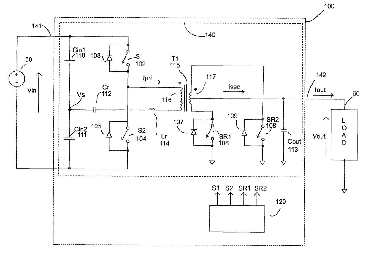
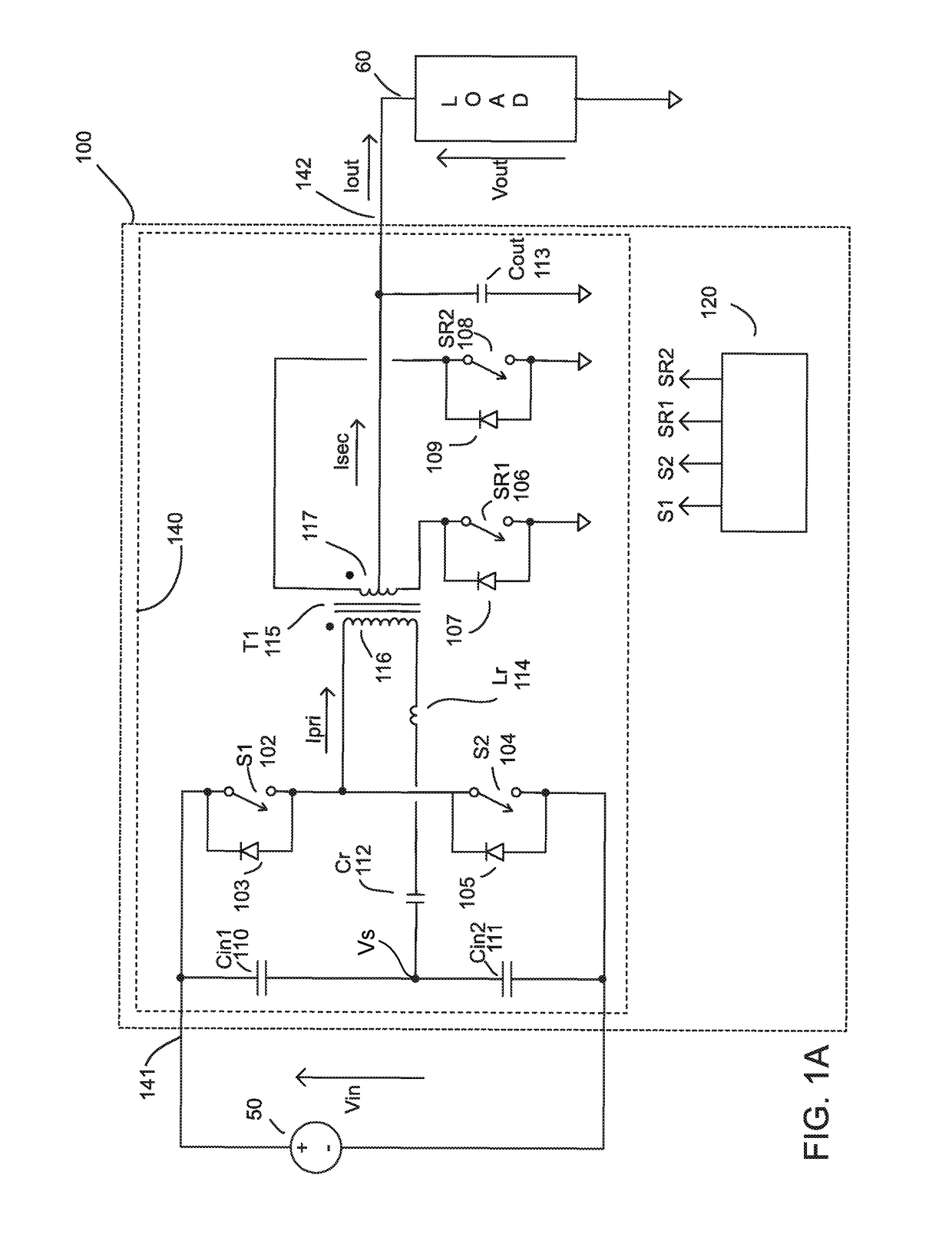
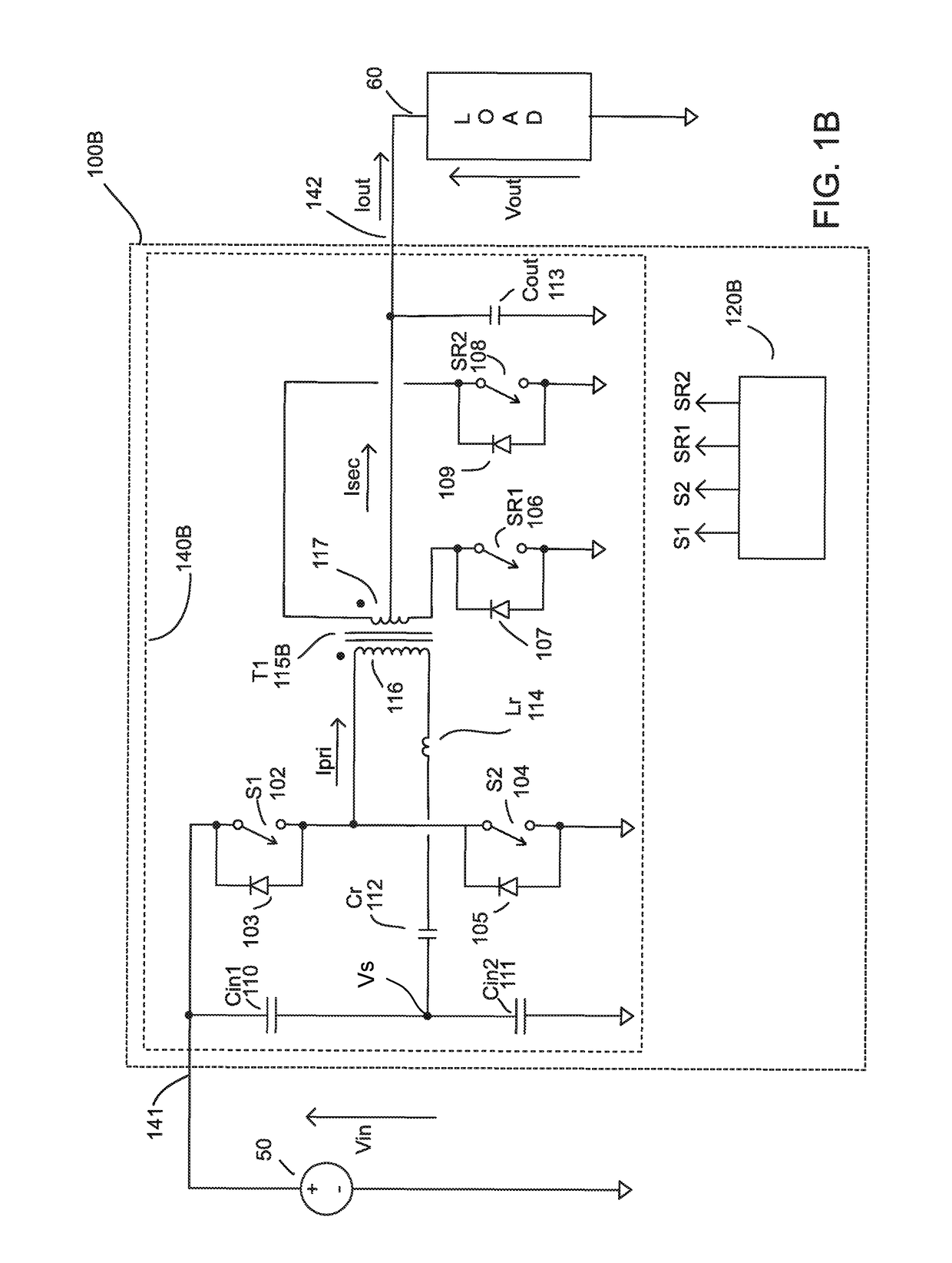
[0022]A DC transformer as defined herein delivers a DC output voltage, Vout, which is a fixed fraction of the voltage, Vin, delivered to its input and optionally provides isolation between its input and its output. The voltage transformation ratio or voltage gain of the DC transformer (defined herein as the ratio, K=Vout / Vin, of its output voltage to its input voltage at a load current) is fixed by design, e.g. by the converter topology, its timing architecture, and the turns ratio of the transformer included within it. A category of DC transformer topologies, called Sine Amplitude Converters (“SACs”), are described in Vinciarelli, Factorized Power Architecture with Point of Load Sine Amplitude Converters, U.S. Pat. No. 6,930,893 issued Aug. 16, 2005; and in Vinciarelli, Point of Load Sine Amplitude Converters and Methods, U.S. Pat. No. 7,145,786 issued on Dec. 5, 2006, each assigned to VLT, Inc. and incorporated herein by reference in their entirety (the “SAC patents”). As disclose...


PUM


Abstract

A power converter including a transformer, a resonant circuit including the transformer and a resonant capacitor having a characteristic resonant frequency and period, and output circuitry connected to the transformer for delivering a rectified output voltage to a load. Primary switches drive the resonant circuit, a switch controller operates the primary switches in a series of converter operating cycles which include power transfer intervals of adjustable duration during which a resonant current at the characteristic resonant frequency flows through a winding of the transformer. The operating cycles may also include energy recycling intervals of variable duration for charging and discharging capacitances within the converter. A gate driver includes a transformer, a plurality of switches, a current monitor, and a controller that operates the switches in a series of driver operating cycles having adjustable ON periods and adjustable transition periods during which capacitances are resonantly charged and discharged.

Description

TECHNICAL FIELD[0001]This invention relates to the field of electrical power conversion and more particularly to resonant switching power converters.BACKGROUND[0002]Resonant switching power converters may be used as fixed ratio bus converters in power conversion systems to provide scaling of voltages and currents and optionally galvanic isolation. In non-idealized switching converters, i.e., switches used in the converter have parasitic capacitances and inductances, power may be dissipated in a switch when the switch is being turned ON, giving rise to a “switching loss.” Capacitances, both parasitic and lumped, across a switch if not discharged before the switch is turned ON may be a major contributor to switching loss. One way to reduce switching loss in a switching power converter is to use an inductive current to fully or partially charge and discharge the capacitances associated with a switch before turning it ON to achieve full or partial zero voltage switching (“ZVS”) during a...

Claims


Application Information

Patent Timeline
IPC IPC(8): H02M3/335H02M1/08H02M1/00
CPCH02M3/33592H02M1/083H02M2001/0054H02M3/3376Y02B70/10H02M1/0058H02M1/0054
Inventor VINCIARELLI, PATRIZIO
Owner VICOR CORPORATION
Why Eureka
Try Eureka