Device for burring front face of wheel

a front face and wheel technology, applied in the direction of flexible wheel, grinding drive, manufacturing tools, etc., can solve the problems of low linear speed of the central part, affecting the subsequent coating effect, and the place where the burrs are most prone to form, so as to achieve high degree of automation and safe and stable performan

Active Publication Date: 2018-07-17
CITIC DICASTAL
View PDF4 Cites 9 Cited by
  • Summary
  • Abstract
  • Description
  • Claims
  • Application Information

AI Technical Summary

Benefits of technology

[0010]When in use, the device provided by the present invention can perform burring on the central part and spoke of the wheel at different rotation speeds, the problem that the traditional big disc brush has low line speed at the central position when rotating at fixed angular speed is avoided, and the burring effect of the central part is very ideal. Meanwhile, the device provided by the present invention has the characteristics of high degree of automation, advanced technology, and safe and stable performance.

Problems solved by technology

During a production process of an aluminum alloy hub for an automobile, burring a front face of the hub after machining is a very important process; especially at a central riser part, burrs and flash unavoidably exist after machining, and will seriously affect the subsequent coating effect if not being removed in time.
At present, the traditional method for burring the front face of the wheel is to use a big disc brush to directly burr the front face, this way has the problem that when the angular speed is a constant, the linear speed of the central part is relatively low, but the part is the place where burrs are most liable to form.

Method used


Image

  • Device for burring front face of wheel
  • Device for burring front face of wheel
  • Device for burring front face of wheel

Examples


Embodiment Construction

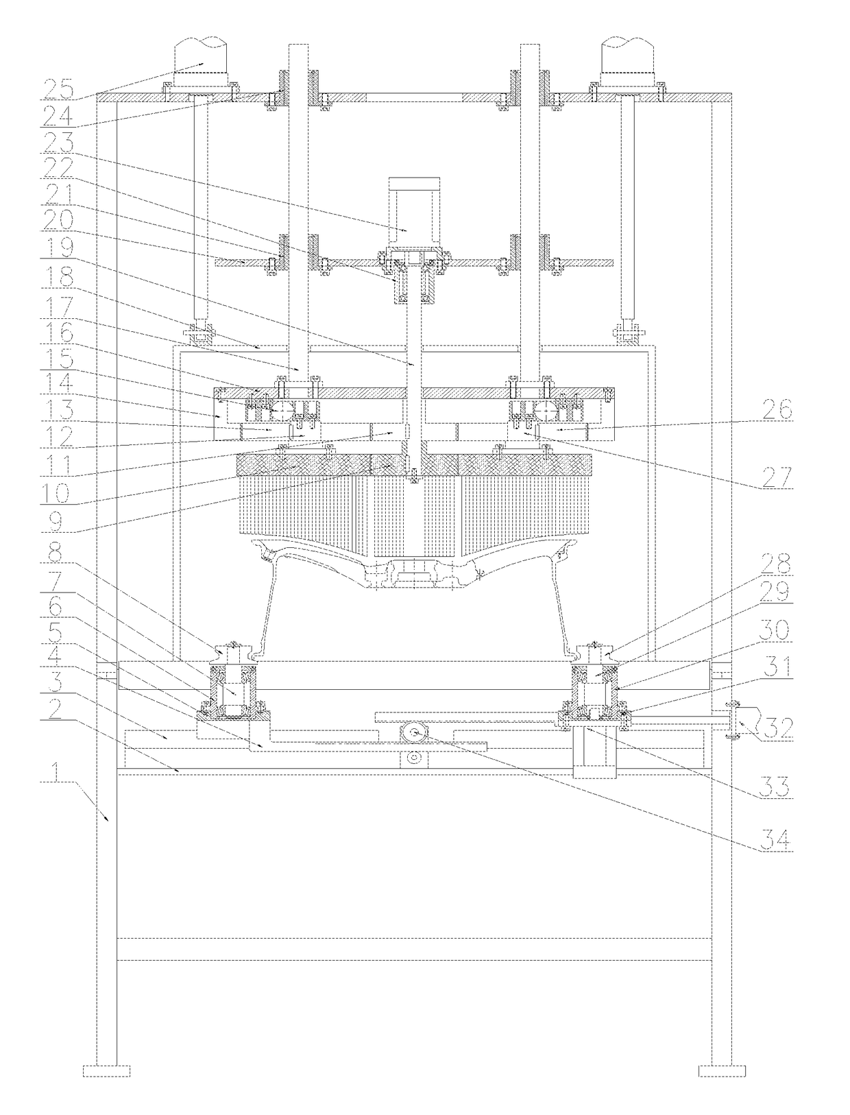
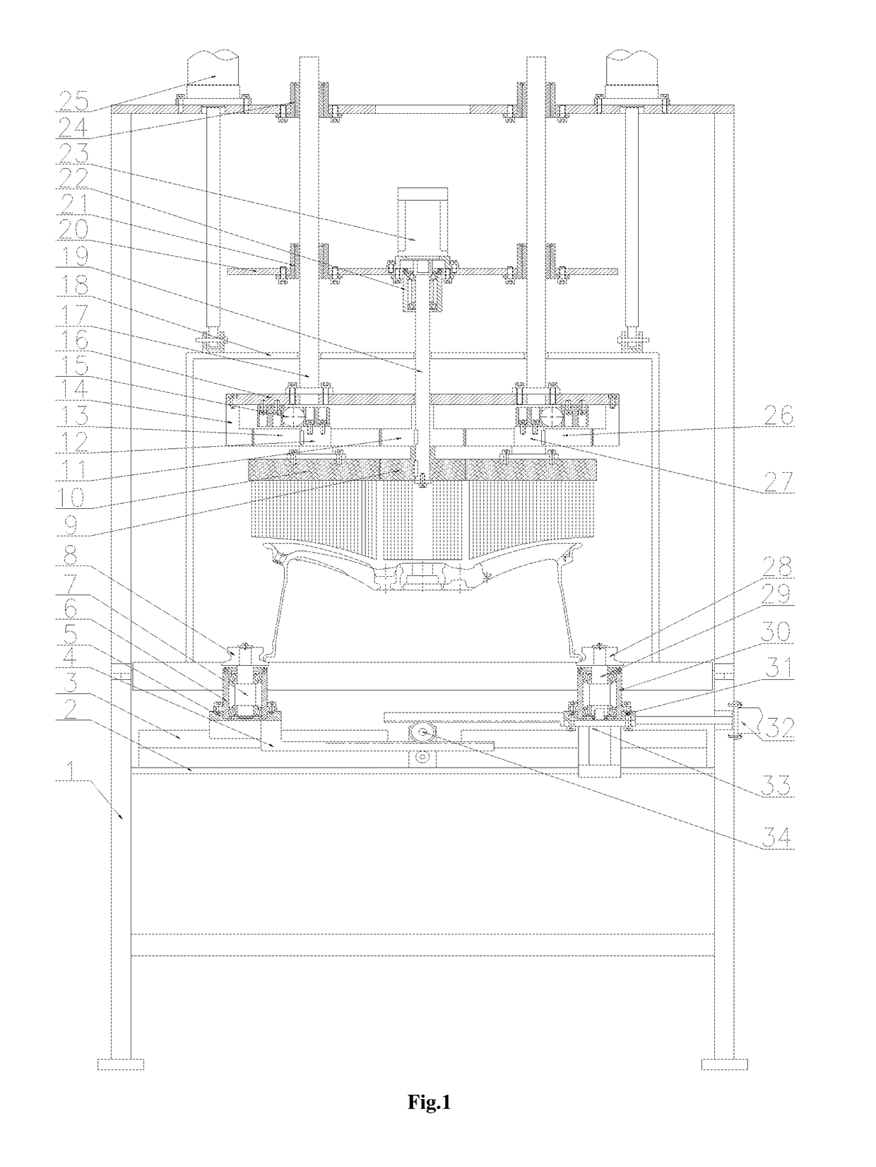
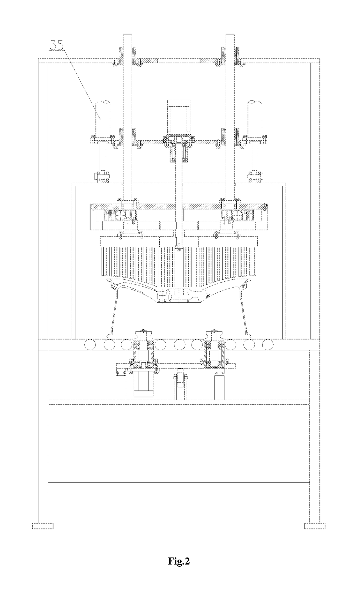
[0014]In the following, the details and working conditions of a specific device provided by the present invention are described in combination with figures.

[0015]The device is composed of a rack 1, a support plate 2, a guide rail 3, gear racks 4, a left sliding plate 5, left bearing blocks 6, left shafts 7, left rolls 8, a central brush 9, an outer ring brush 10, a gear I 11, a shaft I 12, a gear II 13, a gear ring 14, a swivel 15, a fixed plate 16, guide pillars 17, a dust cover 18, a shaft II 19, a lifting plate 20, lower sliding sleeves 21, a lower bearing block 22, a motor 23, upper sliding sleeves 24, air cylinders I 25, a gear III 26, a shaft III 27, right rolls 28, right shafts 29, right bearing blocks 30, a right sliding plate 31, a clamping air cylinder 32, a servo motor 33, synchronous gears 34 and air cylinders II 35. The left sliding plate 5 on which the two left bearing blocks 6 are installed and under which the two gear racks 4 are installed is fixed above the support ...


PUM


Abstract

The present invention relates to a device for burring a front face of a wheel. The device is composed of a rack, a motor, a guide rail, air cylinders, brushes and the like. A sensor enables the wheel to be positioned on a roller way, a clamping air cylinder drives left rolls and right rolls via synchronous gears and gear racks to clamp the wheel, a servo motor drives the wheel to rotate at relatively low speed under the clamped condition, and the rotation direction of the wheel is opposite to that of the brushes; the air cylinders I enable a dust cover to go down, and the motor drives a gear I and a central brush via a shaft II to rotate at relatively high speed; the gear I drives a gear II and a gear III to rotate simultaneously at slightly slow speed, so as to drive an outer ring brush to also rotate at relatively slow speed; and the air cylinders II drive the central brush and outer ring brush to go down, and burring can be performed once the central brush and outer ring brush contact the front face of the wheel. When in use, the device provided by the present invention can burr the central part and the spoke of the wheel at different rotation speeds, and the problem that the traditional big disc brush has low linear speed at the central position when rotating at fixed angular speed is avoided.

Description

[0001]This application claims priority from CN 201511006474.8, filed on Dec. 29, 2015, the entire content of which is incorporated herein by reference.TECHNICAL FIELD[0002]The present invention relates to a burring device, in particular to a device for burring a front face of a wheel.BACKGROUND ART[0003]During a production process of an aluminum alloy hub for an automobile, burring a front face of the hub after machining is a very important process; especially at a central riser part, burrs and flash unavoidably exist after machining, and will seriously affect the subsequent coating effect if not being removed in time. At present, the traditional method for burring the front face of the wheel is to use a big disc brush to directly burr the front face, this way has the problem that when the angular speed is a constant, the linear speed of the central part is relatively low, but the part is the place where burrs are most liable to form.SUMMARY OF THE INVENTION[0004]An object of the pr...

Claims


Application Information

Patent Timeline
Patent Type & Authority Patents(United States)
IPC IPC(8): B24B9/04
CPCB24B9/04B24B41/06B24B47/12B24B55/06B24B29/005B24B29/04B24B41/067B24D13/145
Inventor XUE, BOWENGUO, JIANDONG
Owner CITIC DICASTAL
Why Eureka
Try Eureka