
Polishing pad, polishing apparatus and method for manufacturing polishing pad

a polishing pad and polishing technology, applied in the direction of lapping tools, etc., can solve the problems of uneven thickness, uneven thickness, and increased so as to achieve uniform thickness, uniform buffer force, and uniform friction between the polishing pad and the substrate.

Inactive Publication Date: 2018-07-17
SAN FANG CHEM IND
View PDF12 Cites 2 Cited by
  • Summary
  • Abstract
  • Description
  • Claims
  • Application Information

AI Technical Summary

Benefits of technology

The solution achieves uniform pressure distribution and increased substrate surface flatness, enhancing the polishing process by maintaining a stable polishing surface removal rate and extending the life of the polishing pad.

Problems solved by technology

However, in the manufacture of the non-woven fabric, control of the thickness uniformity is not easy, so using the buffer sheet with the non-woven fabric as the main body may often cause many problems due to the non-uniform thickness.
For example, when the polishing pad withstands the pressure, the non-uniform thickness of the non-woven fabric causes the diversity of the density in different areas of the buffer sheet and yields the diversity of the compression rate.
The area where the compression rate is smaller or the thickness is thicker may lead the friction between the polishing pad and the substrate to become bigger, and the polishing pad also wears faster.
Due to the difference of the wear degree, a surface of the polishing pad becomes more uneven that causes unstable polishing surface removal rate of the substrate and poor flatness, and forms a defective product finally.

Method used


Image

  • Polishing pad, polishing apparatus and method for manufacturing polishing pad
  • Polishing pad, polishing apparatus and method for manufacturing polishing pad
  • Polishing pad, polishing apparatus and method for manufacturing polishing pad

Examples


Embodiment Construction

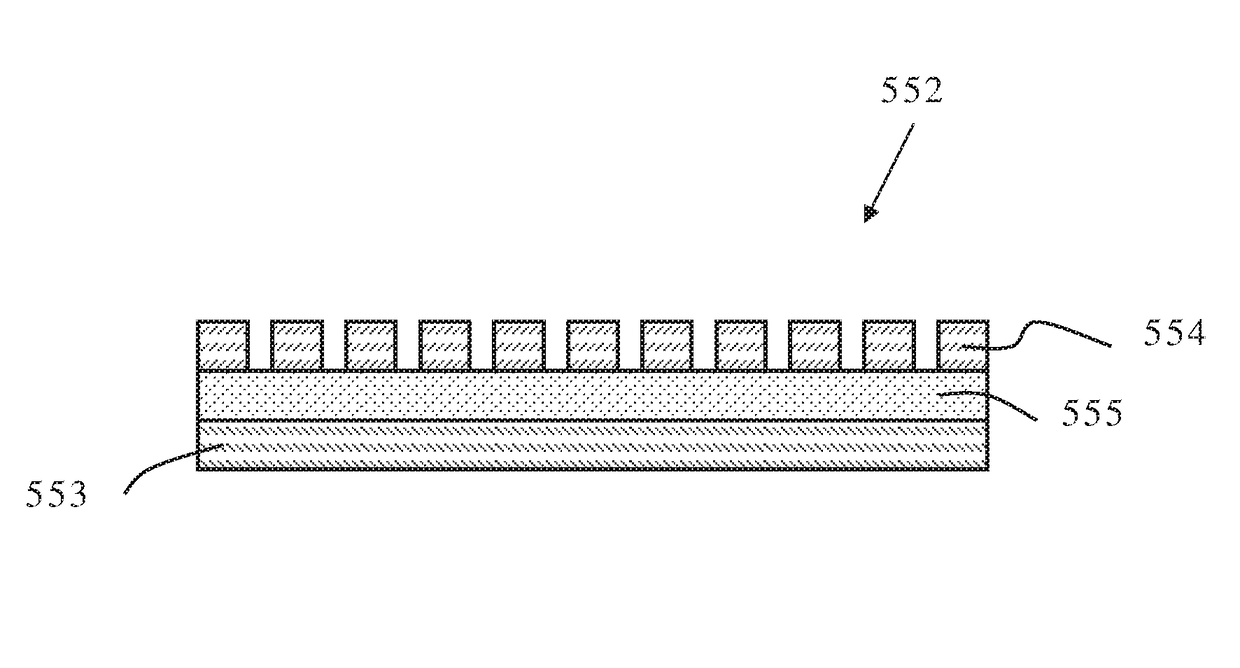
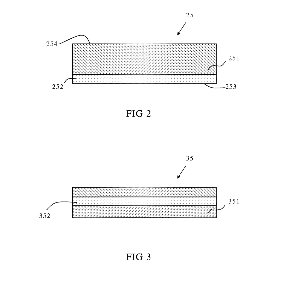
[0031]The invention provides a polishing pad 8 (as shown in FIG. 8) comprising a polishing sheet 81 and a buffer sheet 82, wherein the buffer sheet comprises:[0032]a main body comprising a plurality of first non-oriented fibers; and[0033]a pressure distribution sheet comprising a plurality of first oriented fibers and a plurality of second oriented fibers, wherein all the first oriented fibers are arranged in a first direction; all the second oriented fibers are arranged in a second direction; the first direction intersects with the second direction; and the first oriented fibers and / or the second oriented fibers intersect with at least one of the first non-oriented fibers.

[0034]The term “polishing pad” as used herein refers to a pad for planarizing a substrate in a process of chemical mechanical polishing, which is used against a substrate; wherein the polishing pad repeats the action regularly to polish the substrate and coordinates with the slurry having fine particles for wearin...


PUM


Abstract

The present invention relates to a polishing pad comprising a buffer sheet containing a pressure distribution sheet. The invention also relates to a polishing apparatus and a method for manufacturing a polishing pad.

Description

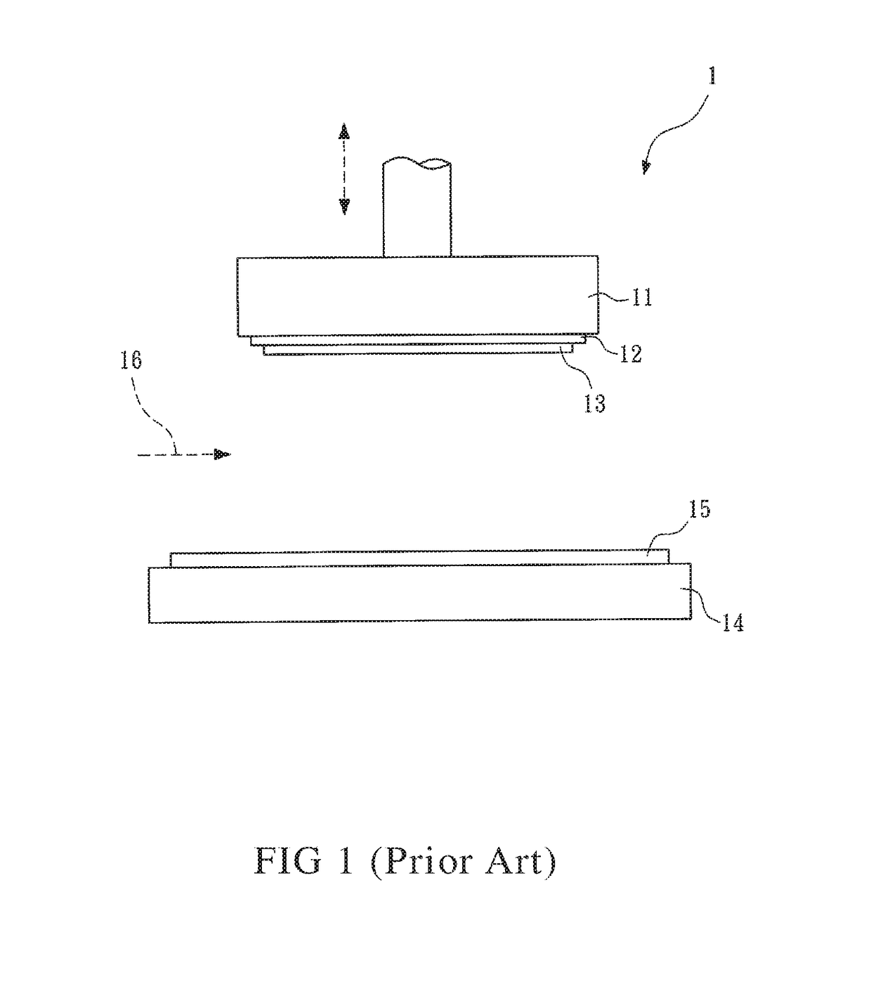
BACKGROUND OF THE INVENTION[0001]1. Field of the Invention[0002]The present invention relates to a polishing pad, a polishing apparatus and a method for manufacturing a polishing pad.[0003]2. Description of the Related Art[0004]Polishing generally refers to a wear control for a preliminary coarse surface in a process of chemical mechanical polishing (CMP), which makes the slurry containing fine particles evenly dispersed on the upper surface of a polishing pad, and at the same time places a substrate against the polishing pad and then rubs the substrate repeatedly with a regular motion. The substrate may be objects such as a semiconductor, a storage medium substrate, an integrated circuit, an LCD flat-panel glass, an optical glass and a photoelectric panel. During the polishing process, a mounting must be used for carrying and mounting the substrate, and the quality of the mounting directly influences the polishing effect of the substrate.[0005]FIG. 1 shows a schematic view of a pol...

Claims


Application Information

Patent Timeline
Patent Type & Authority Patents(United States)
IPC IPC(8): B24B37/22B24B37/24
CPCB24B37/24B24B37/22
Inventor FENG, CHUNG-CHIHYAO, I-PENGHUNG, YUNG-CHANGLIU, WEI-TE
Owner SAN FANG CHEM IND
Learn More