Integrated gas oil separation plant for crude oil and natural gas processing

a gas oil separation and crude oil technology, applied in the field of gas oil separation plant (gosp) technology, can solve problems such as instability and safety hazards

Active Publication Date: 2018-07-17
SAUDI ARABIAN OIL CO
View PDF24 Cites 8 Cited by
  • Summary
  • Abstract
  • Description
  • Claims
  • Application Information

AI Technical Summary

Benefits of technology

[0006]Embodiments of systems and methods of the disclosure provide atmospheric pressure gas and low pressure gas direct contact feed streams, originating from atmospheric pressure and low pressure compressors (following knockout drums), for mixing with incoming crude oil for processing. Systems and methods eliminate the need for gas compression after coolers and utilize compression heat to directly preheat crude oil inlet streams by mixing, which aids in water emulsion separation from crude oil and reduces capital expenditures and operating costs.
[0015]Additionally disclosed is an integrated gas oil separation method, and the method includes the steps of: separating crude oil into a high pressure off-gas, an oily water output, and a partially dry, partially degassed crude oil output; separating the partially dry, partially degassed crude oil output into a low pressure off-gas, and a further partially dry, further partially degassed crude oil output; removing condensates from the low pressure off-gas; and compressing the low pressure off-gas. The method further includes the steps of separating the further partially dry, further partially degassed crude oil output into an atmospheric pressure off-gas, an oily water output, and a substantially degassed, partially dry crude oil output; removing condensates from the atmospheric pressure off-gas; compressing the atmospheric pressure off-gas; increasing the temperature of the crude oil with the compressed low pressure off-gas; and increasing temperature of the partially dry, partially degassed crude oil output with the compressed atmospheric pressure off-gas.

Problems solved by technology

However, a large pressure reduction in a single separator will cause flash vaporization, leading to instability and safety hazards.

Method used


Image

  • Integrated gas oil separation plant for crude oil and natural gas processing
  • Integrated gas oil separation plant for crude oil and natural gas processing
  • Integrated gas oil separation plant for crude oil and natural gas processing

Examples


Embodiment Construction

[0025]While the disclosure will be described in connection with several embodiments, it will be understood that it is not intended to limit the disclosure to those embodiments. On the contrary, it is intended to cover all the alternatives, modifications, and equivalents as may be included within the spirit and scope of the disclosure defined by the appended claims.

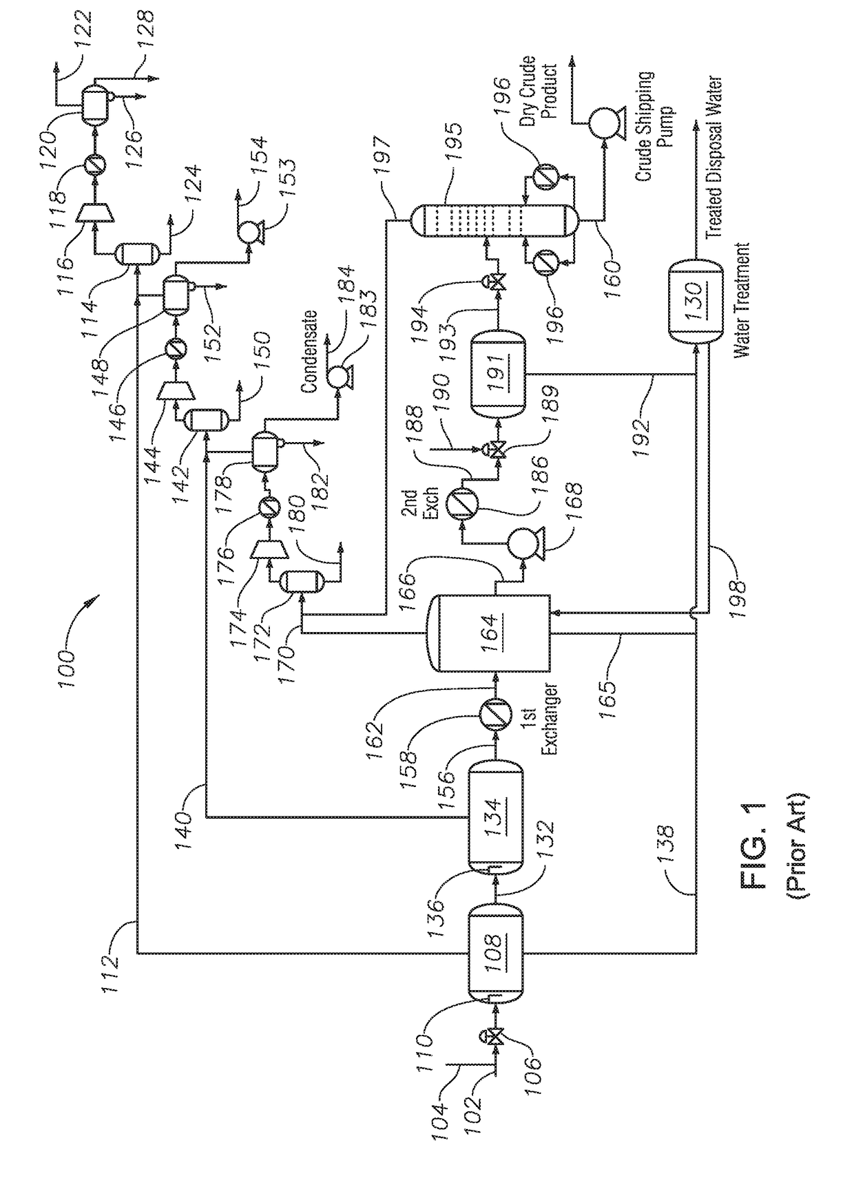
[0026]Referring first to FIG. 1, a schematic diagram is provided showing a conventional GOSP system and process for processing crude oil and gas from production wells in a hydrocarbon-bearing formation. Conventional GOSP's suffer from many deficiencies including low product yield, inefficient use of available heat sources such as for example the discharge streams of compressors, many separate units being used to meet product specification, high operating costs due to heating requirements, a large spatial footprint, and high capital cost.

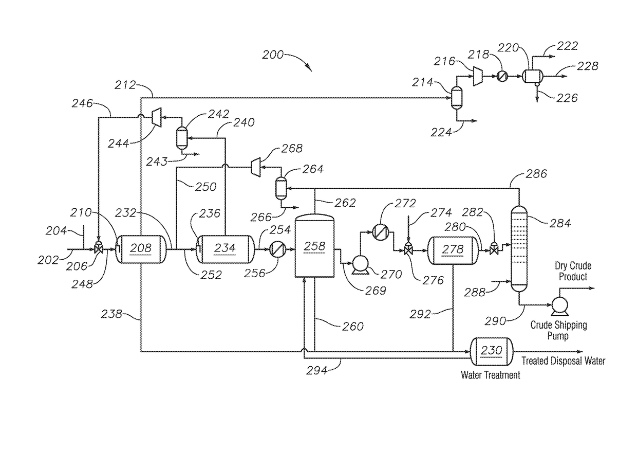
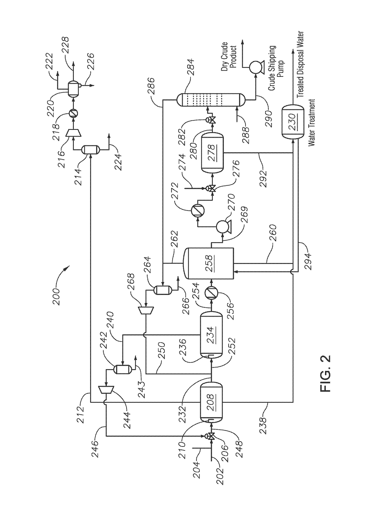
[0027]In general, a GOSP is a continuous separation system and process that includes a ...


PUM

PropertyMeasurementUnit
true vapor pressureaaaaaaaaaa
operating pressureaaaaaaaaaa
temperatureaaaaaaaaaa

Abstract

Systems and methods of integrated gas oil separation are disclosed. Systems include a high pressure production trap (HPPT), a low pressure production trap (LPPT), a low pressure degassing tank (LPDT), a first knockout drum (KOD) fluidly coupled to the LPDT and operable to accept an atmospheric pressure off-gas from the LPDT, an atmospheric pressure compressor fluidly coupled to the first KOD and operable to compress the atmospheric pressure off-gas to introduce the atmospheric pressure off-gas from the LPDT into the LPPT inlet feed stream, a second KOD fluidly coupled to the LPPT and operable to accept a low pressure off-gas from the LPPT, and a low pressure compressor fluidly coupled to the second KOD and operable to compress the low pressure off-gas to introduce the low pressure off-gas from the LPPT into the crude oil inlet feed stream.

Description

BACKGROUNDField[0001]The present disclosure relates to gas oil separation plant (GOSP) technology. In particular, the disclosure relates to integrating the three-phase separation function of knockout drums (KOD's) with existing crude oil separation equipment to create efficient GOSP systems and processes.Description of Related Art[0002]In general, a GOSP is a continuous separation process used to refine crude oil, which includes a high pressure production trap (HPPT), a low pressure production trap (LPPT), a low pressure degassing tank (LPDT), a dehydrator unit, first and second stage desalting units, a water / oil separation plant (WOSEP), a stabilizer column, centrifugal pumps, heat exchangers, and reboilers. In a GOSP, vessel pressure is often reduced in several stages to allow the controlled separation of volatile components, such as entrained vapors. Goals of a GOSP include achieving maximum liquid recovery with stabilized oil separated from gas, and water separated from gases an...

Claims


Application Information

Patent Timeline
Patent Type & Authority Patents(United States)
IPC IPC(8): C10G33/00C10G7/00C10G5/06
CPCC10G7/00C10G5/06C10G33/00C10G2300/208C10G2300/205C10G2300/207C10G31/06C10G31/08C10G33/02C10G53/02C10G7/04
Inventor SOLIMAN, MOHAMEDSALU, SAMUSIDEEN ADEWALEAL-ZAHRANI, TALALANSARI, NISAR AHMAD K.
Owner SAUDI ARABIAN OIL CO
Why Eureka
Try Eureka