Portable blood count monitor

a blood count monitor and portable technology, applied in the field of portable blood count monitors, can solve the problems of inability to reach the general public, difficulty in use, cost, etc., and achieve the effect of reducing the difficulty of use, and improving the accuracy of blood coun

Inactive Publication Date: 2018-07-17
RGT UNIV OF CALIFORNIA +1
View PDF38 Cites 21 Cited by
  • Summary
  • Abstract
  • Description
  • Claims
  • Application Information

AI Technical Summary

Benefits of technology

[0008]In some embodiments, the invention provides a kit comprising: a) a device comprising: i) a slide configured to receive a body fluid, wherein the slide comprises a first chamber and a second chamber; and ii) an imaging system configured to acquire visual data from the slide; b) a first reagent capable of detecting a first cell type in the body fluid; and c) a second reagent capable of detecting a second cell type in the body fluid.

Problems solved by technology

Home testing is frustrated by the complexity of medical instruments, difficulty of use, cost, and unavailability to the general public.
Several challenges exist in creating and providing systems, devices, and methods that can offer laboratory quality testing outside of a laboratory.

Method used


Image

  • Portable blood count monitor
  • Portable blood count monitor
  • Portable blood count monitor

Examples


example 1

f the Invention

[0086]Flowchart 500 (FIG. 5) illustrates a method for analyzing a body fluid comprising the steps of providing the body fluid to a chamber, detecting an analyte in the body fluid with a reagent, acquiring visual data from the slide, and analyzing the visual data. The example illustrates a representative embodiment wherein the body fluid is a blood sample.

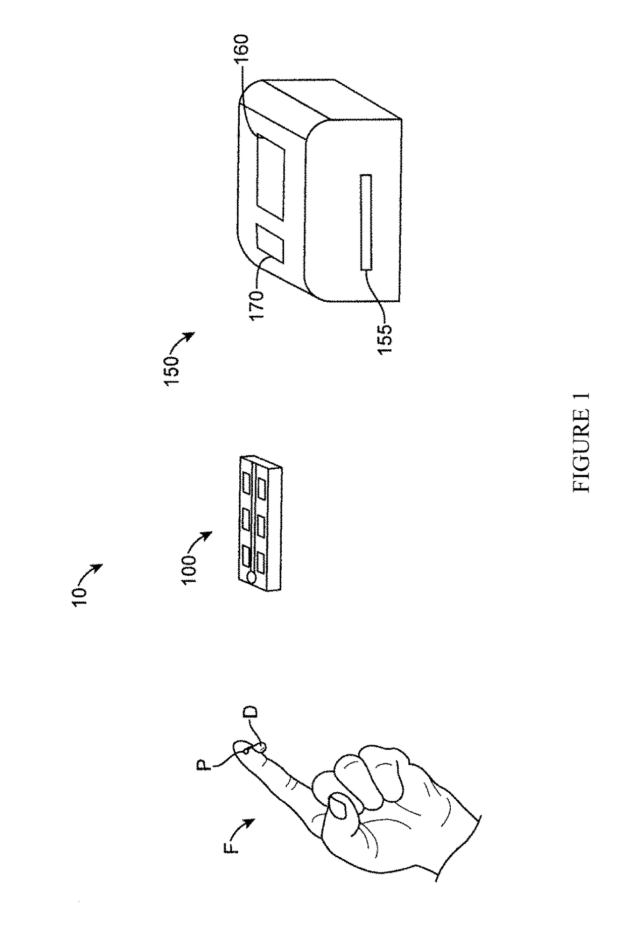
[0087]In 505 a subject provides a small volume of blood sample to a chamber. A subject can use a finger-prick needle to penetrate the skin and to retrieve a drop of blood. A relatively small volume of blood is required, and a drop of blood can be, for example, a sub-microliter volume of blood or a volume of blood between about 1 μL and about 5 μL. The subject can add the drop of the blood to a chamber, such as the chambers described herein 510.

[0088]A chamber can be pre-packaged with a reagent that stains the blood sample 515. The reagent can comprise, for example, a fluorescent dye, such as acridine orange, and a sur...

example 2

f the Invention

[0093]A system of the invention can comprise a plurality of imaging systems, configured in distinct manners to acquire visual data from a device of the invention.

[0094]FIG. 7 shows a block diagram of a system 104 and device for analyzing a body fluid. System 104, particularly the automated portable slide analyzer 150A, can be similar to the system 10 and the automated portable slide analyzer 150, described with reference to FIG. 3. However, this example illustrates a system 104 wherein the blood collection and analysis slide 100R moves via rotation instead of translation to allow an imaging system to capture visual data from different locations within a chamber or within distinct chambers.

[0095]The system 104 comprises a motor 100M configured to couple slide 100R and rotate slide 100R for visualizing a desired sampling chamber of the slide 100R. As shown in FIG. 7, the motor 100M can align the sampling chamber 115R of the slide 100R with the light sources 300, 305, as...

example 3

Applications of a Device, System, and Method of the Invention

[0104]In order to assess the quality of sample preparation, image acquisition, and image analysis with the devices, systems, and methods of the invention, a study of 13 healthy and unhealthy volunteers was performed, and a comparative analysis between the results obtained with the invention and a commercial automated hematology analyzer was conducted. For each volunteer, blood was drawn once and measured: 1) on a clinical automated hematology analyzer; 2) and using an embodiment of the invention described herein.

[0105]FIG. 9 is a schematic of a system for the analysis of a body fluid applied to the analysis of a blood sample. Panel A illustrates a sample preparation from sub-microliter volumes of whole-blood. Samples were prepared by diluting sub-microliter volumes of whole blood 20 times in a first reagent, and then injecting the blood sample into a 100-μm-thick chamber of the invention. The first reagent consisted of pho...


PUM

PropertyMeasurementUnit
total massaaaaaaaaaa
distanceaaaaaaaaaa

Abstract

This disclosure describes the development of a sample preparation, measurement, and analysis method that permits accurate characterization of red blood cells, platelets, and white blood cells, including a 3-part differential of the white blood cells count, to be performed on small volumes of a biological sample. This method is compatible with compact and portable instrumentation that permits the sample collection to be performed in a subject's home and analysis to be performed elsewhere by transmission of the data to a laboratory or doctor's office.

Description

CROSS-REFERENCE[0001]This application claims the benefit of U.S. Provisional Application No. 61 / 890,071, filed on Oct. 11, 2013; U.S. Provisional Application No. 61 / 878,431, filed on Sep. 16, 2013; and U.S. Provisional Application No. 61 / 780,732, filed on Mar. 13, 2013, the contents of each of which is incorporated herein by reference in its entirety.STATEMENT AS TO FEDERALLY SPONSORED RESEARCH[0002]This invention was made with partial government support under an Acceleration of Innovation Research grant awarded by the National Science Foundation (NSF Accelerating Innovation Research Grant No. 1127888, entitled “Creation of an Ecosystem for Biophotonic Innovation” and dated Aug. 1, 2011 to Jul. 31, 2013), as well as from the Center for Biophotonics Science and Technology, a designated NSF Science and Technology Center managed by the University of California, Davis, under Cooperative Agreement No. PHY0120999. The government has certain rights in the invention.BACKGROUND[0003]Home or ...

Claims


Application Information

Patent Timeline
Patent Type & Authority Patents(United States)
IPC IPC(8): G01N31/22G01N33/574G01N33/50
CPCG01N33/5017G01N33/57438
Inventor SMITH, ZACHARYGAO, TINGJUANLANE, STEPHENWACHMANN-HOGIU, SEBASTIANDWYRE, DENISHEIFETZ, LAURENCEHOOD, JAMESMATTHEWS, DENNISTATSUKAWA, KEITH
Owner RGT UNIV OF CALIFORNIA
Why Eureka
Try Eureka