Automatic push-out to avoid range of motion limits

a push-out and automatic technology, applied in the direction of machine supports, applications, surgical instruments, etc., can solve the problems of still being play or limited movement of the joint, and the control unit may delay the application of the joint drive or brake system for at least a delay duration

Active Publication Date: 2018-07-24
INTUITIVE SURGICAL OPERATIONS INC
View PDF56 Cites 42 Cited by
  • Summary
  • Abstract
  • Description
  • Claims
  • Application Information

AI Technical Summary

Benefits of technology

[0010]In many embodiments, it may be desirable to keep one, some, or all joints of the kinematic chain off a “hardstop” or physical range of motion limit (ROM limit) associated with the joint or otherwise maintain a desired range of motion for one, some, or all joints of the kinematic chain when exiting the set-up mode. For example, it may be beneficial to keep joints of the kinematic chain off a ROM limit as a safety feature of a surgical system. In a system with redundant degrees of freedom (DOFs), if a relatively more distal joint is at a ROM limit (e.g., fully compressed), and then one or more relatively more proximal joints are moved in a DOF redundant to the distal joint, the arm distal of the distal joint may exert extremely high forces against an object (e.g., operating table or the like) or patient. Accordingly, it may be beneficial to push the joint from a physical ROM limit or to otherwise maintain a desired range of motion of the joint so as to provide a buffering zone between the joint and the physical ROM limit. While drive or brake systems may be actuated to maintain a joint in a resting and / or locked position, there may still be play or limited movement of the joint, for example, if the joint experiences outside forces that exceed the drive or brake forces. Thus the buffering zone may absorb and / or counteract joint motion toward the ROM limit and provide an additional layer of safety measures for the surgical system.
[0026]The computing unit may clear the error signal after the joint is moved to a position within the range of motion between the first software defined range of motion limit and the second software defined range of motion limit and may allow for the reapplication of the driving or the braking by the drive or brake system of the set-up linkage with the joint positioned between the first and second software defined range of motion limits.
[0031]In some embodiments, the computing unit may clear the error signal after the joint is moved outside the first threshold proximity of the first range of motion limit and may then allow for the reapplication of the driving or the braking by the drive or brake system of the set-up linkage with the joint outside the first threshold proximity of the first range of motion limit.
[0032]In further embodiments, the at least one joint includes one or more springs at the range of motion limit that compress when the joint is moved within the first threshold proximity of the first range of motion limit. When the driving or braking by the drive or brake system of the set-up linkage is reapplied with the joint positioned within the first threshold proximity of the first range of motion limit, operator actuation of the actuatable input may briefly halt the driving or braking by the drive or brake system and may thereby allow the one or more springs positioned at the first range of motion limit to automatically push the joint out from the first threshold proximity of the first range of motion limit. The computing unit may then automatically reapply the driving or braking by the drive or brake system after the joint is pushed out from the first threshold proximity of the first range of motion limit.

Problems solved by technology

While drive or brake systems may be actuated to maintain a joint in a resting and / or locked position, there may still be play or limited movement of the joint, for example, if the joint experiences outside forces that exceed the drive or brake forces.
When a user manually pushes the joint into the spring against the physical ROM limit and signals to reengage a drive or brake system associated with the joint, a control unit may delay an application of the joint drive or brake system for at least a delay duration.

Method used


Image

  • Automatic push-out to avoid range of motion limits
  • Automatic push-out to avoid range of motion limits
  • Automatic push-out to avoid range of motion limits

Examples


Embodiment Construction

[0064]In the following description, various embodiments of the present invention will be described. For purposes of explanation, specific configurations and details are set forth in order to provide a thorough understanding of the embodiments. However, it will also be apparent to one skilled in the art that the present invention may be practiced without the specific details. Furthermore, well-known features may be omitted or simplified in order not to obscure the embodiment being described.

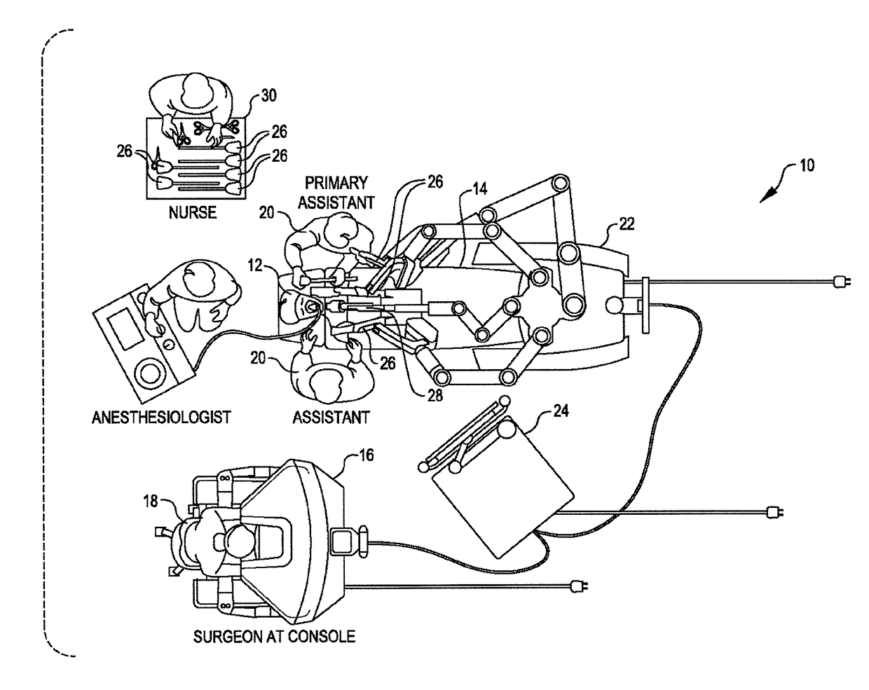
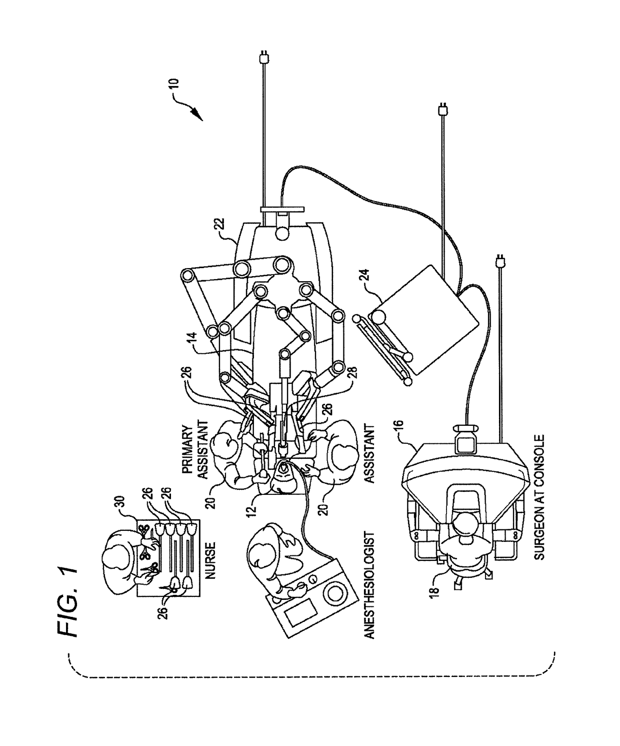
[0065]The kinematic linkage structures and control systems described herein are particularly beneficial in helping system users to arrange the robotic structure of a procedure on a particular patient. Along with actively driven manipulators used to interact with tissues and the like during treatment, robotic surgical systems may have one or more kinematic linkage systems that are configured to support and help align the manipulator structure with the surgical work site. These set-up systems may be...


PUM


Abstract

Robotic and / or surgical devices, systems, and methods include kinematic linkage structures and associated control systems configured to facilitate preparation of the system for use. In some embodiments, actively driven joints will move a platform structure that supports multiple manipulators in response to movement of one of the manipulators, facilitating and expediting the arrangement of the overall system by moving those multiple manipulators as a unit into alignment with the workspace. Systems and methods are also provided to keep one, some, or all joints of the kinematic chain off a hardstop or physical range of motion limit associated with the joint or to otherwise maintain a desired range of motion for one, some, or all joints of the kinematic chain when exiting a set-up mode.

Description

CROSS-REFERENCE TO RELATED APPLICATIONS[0001]This application is a U.S. National Stage application of PCT / US2015 / 021047 filed Mar. 17, 2015; which claims priority to U.S. Provisional Patent Application 61 / 954,452 filed Mar. 17, 2014; and to U.S. Provisional Patent Application 62 / 019,311 filed Jun. 30, 2014, the disclosures of which are incorporated herein by reference.BACKGROUND[0002]Minimally invasive medical techniques are intended to reduce the amount of extraneous tissue that is damaged during diagnostic or surgical procedures, thereby reducing patient recovery time, discomfort, and deleterious side effects. One effect of minimally invasive surgery, for example, is reduced post-operative hospital recovery times. Because the average hospital stay for a standard surgery is typically significantly longer than the average stay for an analogous minimally invasive surgery, increased use of minimally invasive techniques could save millions of dollars in hospital costs each year. While ...

Claims


Application Information

Patent Timeline
Patent Type & Authority Patents(United States)
IPC IPC(8): A61B34/00A61B34/35A61B90/50A61B34/30F16M13/02B25J9/00B25J9/16B25J19/00
CPCA61B34/35A61B34/30A61B90/50B25J9/1689B25J19/0004F16M13/022B25J9/0033A61B2090/5025A61B90/03
Inventor GRIFFITHS, PAUL G.MOHR, PAUL W.ITKOWITZ, BRANDON D.NIXON, THOMAS R.DEVENGENZO, ROMAN
Owner INTUITIVE SURGICAL OPERATIONS INC
Why Eureka
Try Eureka