Drift current coulombic storage apparatus

a coulombic storage and current technology, applied in the direction of conductors, instruments, process and machine control, etc., can solve the problems of preventing the effective flow of current to the power supply, and achieve the effect of improving the performance of the power supply, slowing the velocity of electron drift, and improving the performance of the consumer

Active Publication Date: 2018-07-24
GABRIEL PATENT TECH
View PDF9 Cites 16 Cited by
  • Summary
  • Abstract
  • Description
  • Claims
  • Application Information

AI Technical Summary

Benefits of technology

[0012]The present instant invention improves the performance of consumer and professional electronics designed for audio and video production or reproduction. The apparatus also has beneficial applications for scientific and medical devices that detect low level signals and render them as a visual image on a computer monitor, projector or 3D goggles. The apparatus specifically improves the performance of the power supplies commonly used in consumer electronic devices. These power supplies specifically convert AC (alternating current) power to DC (direct current) power voltages.
[0013]Embodiments of the present invention take advantage of the slow velocity of electron drift by providing a relatively large conductive volume that provides a space to store a “compressed” charge of electrons. Because power supplies pull current in instantaneous pulses, and because the inventive device is positioned very near the power supply, it is able to supply a reserve of electrical charge independent of the inductive impedance of the AC power line. This objective is achieved because the inventive circuit provides a local reserve of power in the form of “electric charge” or Coulomb charge. It mitigates the inductive reactance of the AC power line. When placed near a power supply, the apparatus acts as an instantaneous current reserve. Its operation can be described as analogous to that of a reserve ballast air tank in a compressed air system: instead of storing compressed air locally, the apparatus stores an electrical charge that can be delivered upon demand from the power supply.
[0016]The inventive apparatus is positioned at the AC input to the power supply. The apparatus is most effective when placed as near to the rectifiers as possible.
[0021]Unlike an inductor, the inventive apparatus does not resist a change in instantaneous current flow. Rather, it improves instantaneous current flow. In essence, the apparatus may be considered a unique type of basic electronic circuit component in that it operates entirely differently from either a capacitor or an inductor.

Problems solved by technology

However, the inductive reactance of the AC power line resists this instantaneous draw of current that impedes the effective flow of current flow to the power supply.

Method used


Image

  • Drift current coulombic storage apparatus
  • Drift current coulombic storage apparatus
  • Drift current coulombic storage apparatus

Examples


Embodiment Construction

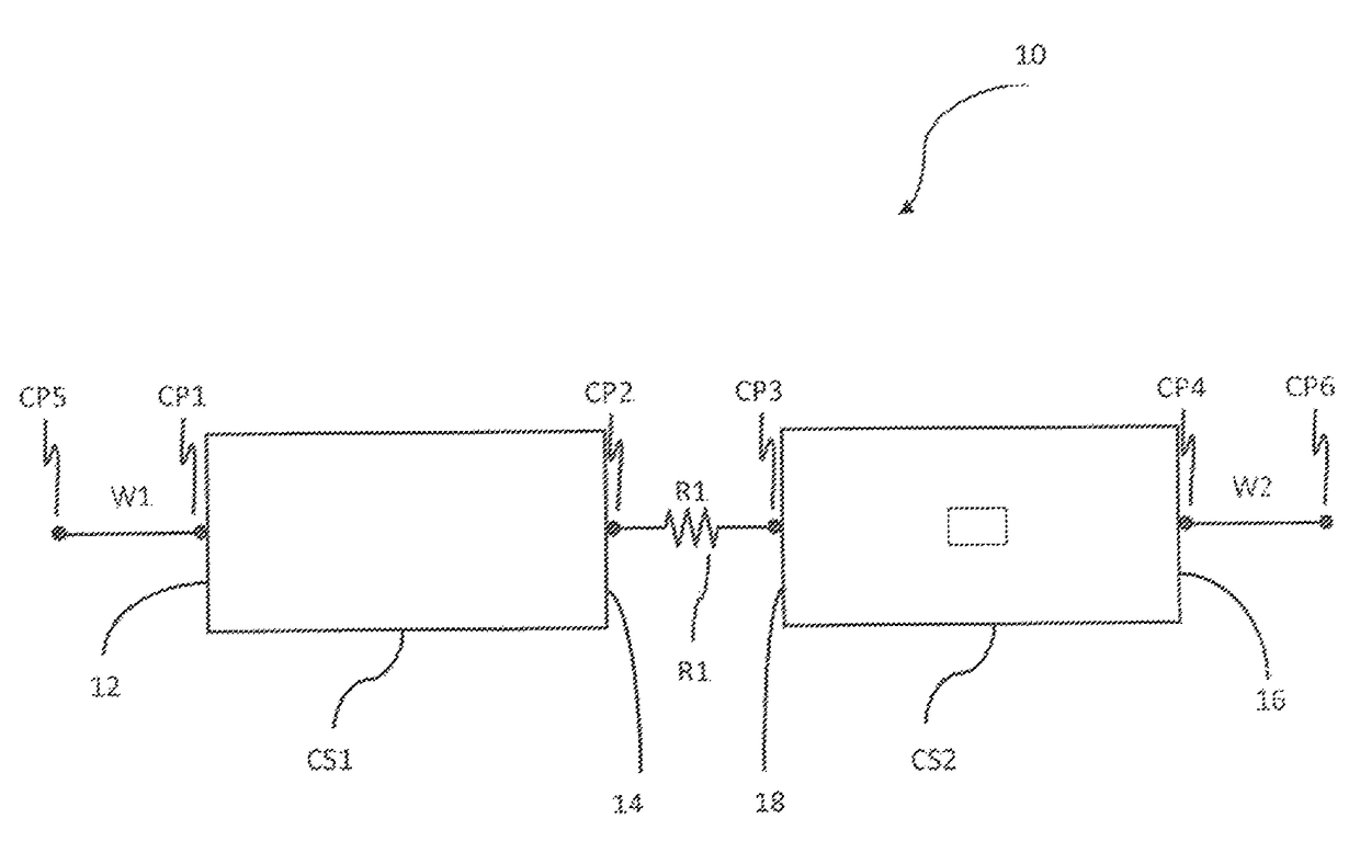
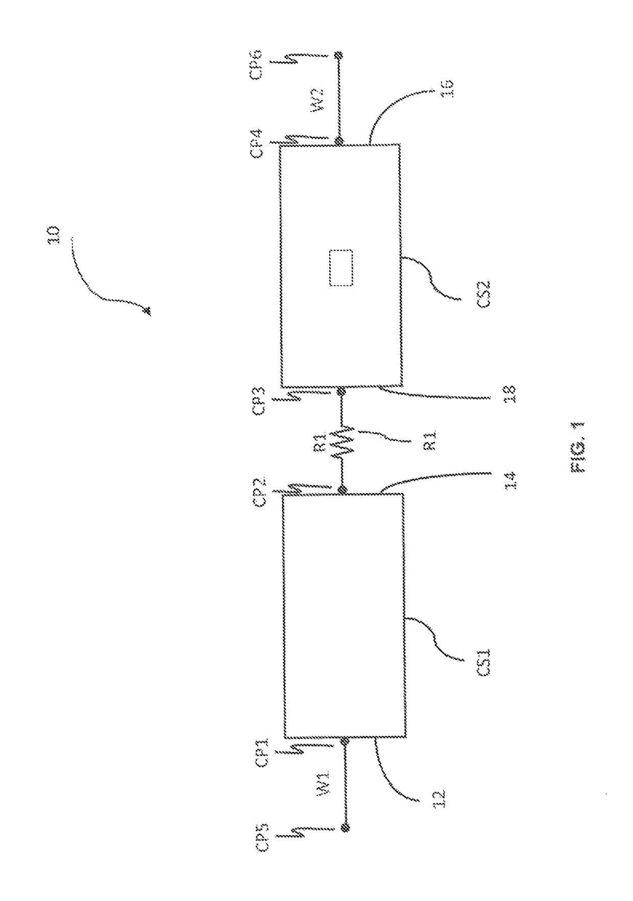
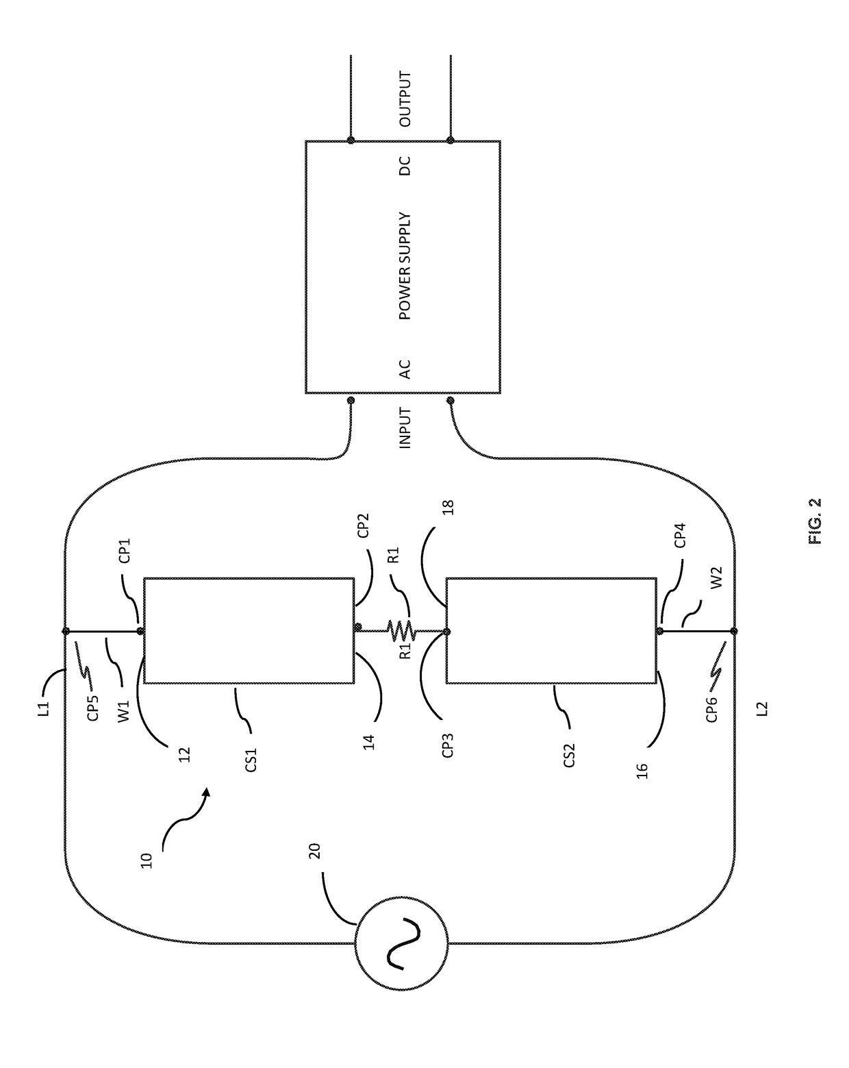
[0026]Referring to FIG. 1 and FIG. 2, it will be seen that in an embodiment, the inventive apparatus 10 consists of first and second conductive strips (foils or very thin plates), CS1 and CS2, respectively, connected in series with a resistor R1 disposed between them.

[0027]FIG. 1 shows that in an embodiment, a first conductive wire W1 is connected at connection point CP1 at a first end 12 of the first conductive strip CS1. The first conductive strip CS1 is connected at its second end 14 in series with resistor R1 at connection point CP2. Resistor R1 is connected in series to the second end 18 of second conductive CS2 strip at connection point CP3. The second conductive strip CS2 is connected in series at its second end 16 with a second conductive wire W2 at connection point CP4.

[0028]The first conductive strip CS1 is bonded at its first end 12 to wire W1. The second conductive strip CS2 is bonded at its first end 16 to wire W2. The first conductive strip is connected in series with ...


PUM


Abstract

A circuit for improving instantaneous current flow in an AC-to-DC power supply for an electronic device, said circuit positioned immediately prior to an AC input for the AC-to-DC power supply and providing a reserve of electrical charge independent of the inductive impedance of the AC power line.

Description

CROSS REFERENCES TO RELATED APPLICATIONS[0001]The present application claims the benefit of U.S. Provisional Patent Application Ser. No. 62 / 274,760, filed Jan. 4, 2016 (Jan. 4, 2016), which is incorporated in its entirety by reference herein.STATEMENT REGARDING FEDERALLY SPONSORED RESEARCH OR DEVELOPMENT[0002]Not applicable.THE NAMES OR PARTIES TO A JOINT RESEARCH AGREEMENT[0003]Not applicable.INCORPORATION BY REFERENCE OF MATERIAL SUBMITTED ON A COMPACT DISC[0004]Not applicable.BACKGROUND OF THE INSTANT INVENTION[0005]Field of the Instant Invention[0006]The present invention relates most generally to power supplies for professional and consumer electronic devices, and more particularly to a circuit or circuit stage to improve power supply efficiency and reliability, and still more particularly to a device to improve instantaneous current flow into an AC / DC power supply commonly used in consumer electronic devices.[0007]Background Discussion[0008]It is well understood that an AC ele...

Claims


Application Information

Patent Timeline
Patent Type & Authority Patents(United States)
IPC IPC(8): G05F1/12H02M7/04
CPCH02M7/04G05F1/12H02M1/4266Y02B70/10H01B1/026H01B1/023
Inventor GABRIEL, CAELIN
Owner GABRIEL PATENT TECH
Why Eureka
Try Eureka