Switching power supply

a technology of switching power supply and inductance element, which is applied in the direction of electric variable regulation, process and machine control, instruments, etc., can solve the problems of affecting the operation of the control circuit. , to achieve the effect of preventing the increase of on time, preventing the decrease of power factor, and maintaining stable operation

Active Publication Date: 2018-07-24
FUJI ELECTRIC CO LTD
View PDF7 Cites 3 Cited by
  • Summary
  • Abstract
  • Description
  • Claims
  • Application Information

AI Technical Summary

Benefits of technology

[0018]The present invention was made in light of the foregoing and aims to provide a switching power supply that makes it possible to maintain a high power factor when a high voltage system (such as a 220V system) is input and also makes it possible to maintain stable operation when a low voltage system (such as a 100V system) is input even during heavy loading states. Accordingly, the present invention is directed to a scheme that substantially obviates one or more of the problems due to limitations and disadvantages of the related art.
[0029]an ON time increase reduction circuit that determines whether the input power source is a relatively low voltage system or a relatively high voltage system, and that reduces an amount by which the ON time of the switching element is increased by the ON time increasing circuit when the input power source is determined to be the relatively low voltage system.
[0030]More specifically, the ON time increasing circuit increases the ON time of the switching element by reducing a slope of the ramp voltage, for example. Moreover, the ON time increase reduction circuit reduces an amount by which a slope of the ramp voltage is decreased by the ON time increasing circuit, for example.
[0036]In the switching power supply configured as described above, the ON time increasing circuit force-increases the ON time Ton of the switching element when the OFF time Toff of the switching element is less than a prescribed value in phase angle regions in which the instantaneous value of the input voltage Vin is low (low voltage phase regions). This makes it possible to prevent the current supplied to the inductance element from decreasing in the low phase regions of the input voltage, thereby preventing decreases in the power factor.
[0037]Moreover, when the error voltage Verr is greater than a prescribed value (that is, when it is determined that the input voltage Vin is a low voltage system (such as 100V)), the ON time increase reduction circuit reduces the amount by which the ON time increasing circuit increases the ON time Ton of the switching element. This prevents the ON time Ton of the switching element from being force-increased by a large amount when the low input voltage Vin is a low voltage system, thereby reducing the occurrence of the abovementioned phenomenon of hunting for the correct ON time Ton. In other words, this prevents excessive increases of the ON time, thereby making it possible to maintain stable operation even when a low voltage system power source is used.
[0039]In particular, the ON time increasing circuit and the ON time increase reduction circuit can be easily integrated together with the main components of the control circuit, such as the ramp voltage generator (ramp generator) and the zero voltage detection circuit. Integrating together the components of the control circuit in this way makes it possible to sufficiently achieve the effects of the present invention simply by replacing an existing switching power supply control circuit such as the one disclosed in Patent Document 3, for example. This makes it possible to provide a stable switching power supply that can be used with a wide variety of input voltages ranging from 100V systems to 220V systems.

Problems solved by technology

However, in the technology disclosed in Patent Document 3, the ON time Ton of the switching element is force-increased when the OFF time Toff is too low.
Therefore, during heavy loading states in which the input voltage Vin is low and the ON time Ton of the switching element is set to a relatively high value, the waveform of the current flowing through the inductance element may become significantly disrupted by any noise that enters the control circuit.
Any noise input to this ZCD terminal may therefore result in a zero-current state being erroneously detected before the inductor current actually becomes equal to zero.
When such a zero-current misdetection occurs, the switching element gets turned ON sooner than necessary, which results in an unexpectedly short OFF time Toff being detected.
This phenomenon of hunting back and forth for the correct ON time Ton disrupts the inductor current waveform.
In other words, the switching power supply is particularly prone to this hunting phenomenon in the phase regions in which the OFF time Toff is set to the lowest values and the switching power supply is most prone to the effects of zero-current misdetections.

Method used


Image

  • Switching power supply
  • Switching power supply
  • Switching power supply

Examples


Embodiment Construction

[0046]Next, a switching power supply according to an embodiment of the present invention will be described with reference to figures.

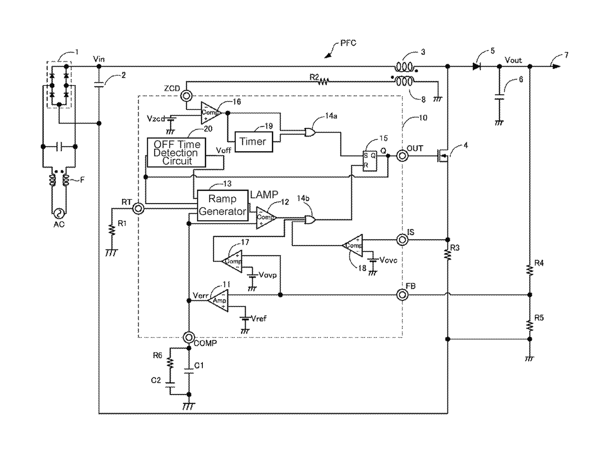
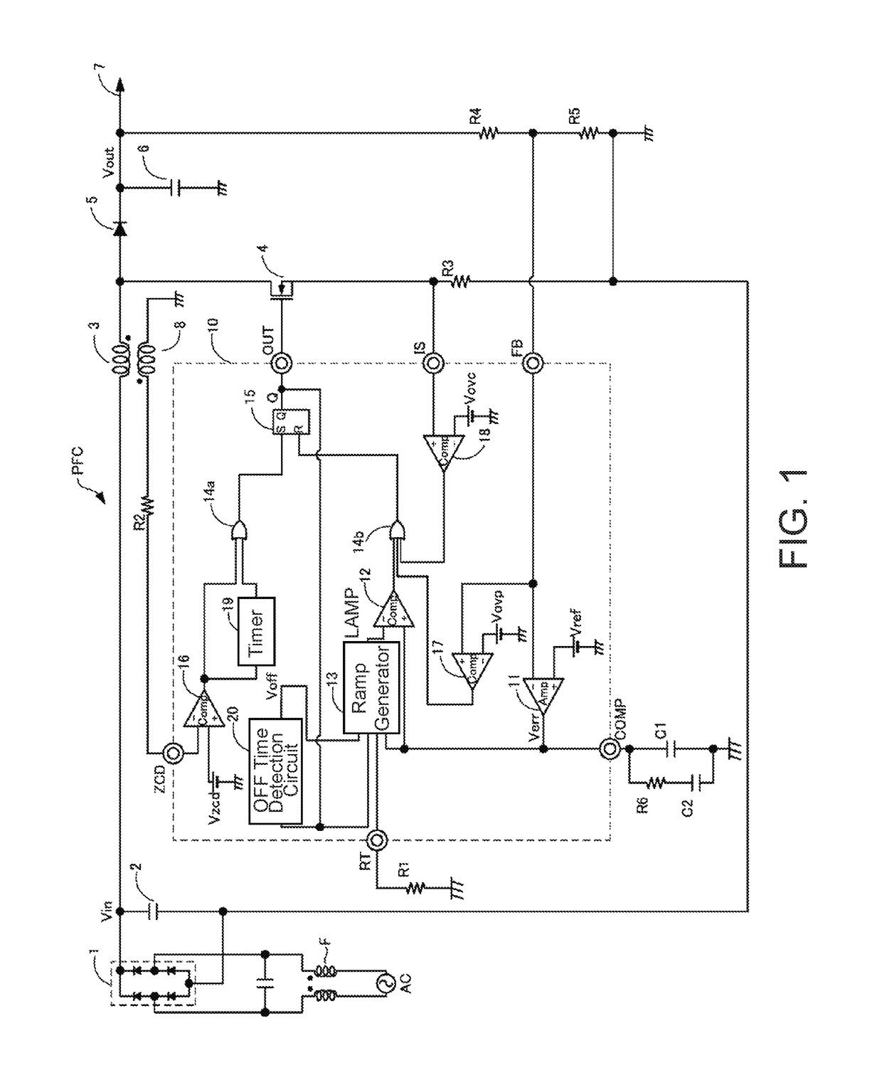
[0047]FIG. 1 schematically illustrates a configuration of a switching power supply (power factor correction converter) PFC according to this embodiment of the present invention. As illustrated in FIG. 1, a rectifier circuit 1 rectifies an AC voltage applied from an input power source AC via an input filter F and inputs the rectified voltage to the switching power supply PFC. The input power source AC is a commercial AC power source of a 100V system or 220V system, and the rectifier circuit 1 is a diode bridge circuit, for example.

[0048]The switching power supply PFC includes an inductance element 3 that is connected to the rectifier circuit 1 and a switching element 4 that, when switched ON, forms a current path to the rectifier circuit 1 via the inductance element 3. The switching power supply PFC also includes a diode 5 that forms a current path betw...


PUM


Abstract

The switching element is turned ON and OFF according to when the current flowing through the inductance element becomes equal to zero and according to an amplified error voltage between the output voltage and a target output voltage. More particularly, the OFF time of the switching element is calculated, and when the OFF time is less than a prescribed value, the ON time of the switching element is increased. Moreover, the amount by which the ON time of the switching element is increased is reduced if the error voltage if greater than a prescribed value.

Description

BACKGROUND OF THE INVENTIONTechnical Field[0001]The present invention relates to a switching power supply that maintains a high power factor when a high voltage is input and also maintains stable operation when a low voltage is input.Background Art[0002]One type of switching power supply is a step-up chopper-type power factor correction (PFC) converter, in which an inductance element is used to create an input current proportional to an input voltage while generating a stable DC output voltage. This type of device offers a number of advantages, such as being small in size, having a high efficiency, and being low in cost.[0003]This type of switching power supply typically includes an inductance element that is connected to an AC input power source via a rectifier circuit and a switching element that, when switched ON, forms a current path to the AC input power source via the inductance element. This type of switching power supply also typically includes a voltage output circuit that ...

Claims


Application Information

Patent Timeline
Patent Type & Authority Patents(United States)
IPC IPC(8): H02M1/42H02M1/00H02M1/08H02M3/156
CPCH02M1/4225H02M1/083H02M3/156Y02B70/126H02M2001/0022H02M2001/0025H02M2001/0064H02M2001/0009Y02B70/10Y02P80/10H02M1/0022H02M1/0025H02M1/0064H02M1/0009
Inventor SUGAWARA, TAKATO
Owner FUJI ELECTRIC CO LTD
Why Eureka
Try Eureka