Method for manufacturing a reinforced composite pipe

a technology of thermoplastic pipes and composite pipes, which is applied in the direction of pipes, mechanical equipment, other domestic objects, etc., can solve the problems of many areas where oil and gas reservoirs exist, damage to the environment, and the inability to exploit them, so as to reduce the risk of leakage, the effect of easy deployment and or removal of the piping system

Active Publication Date: 2018-07-31
COMPOSITE FLUID TRANSFER
View PDF28 Cites 3 Cited by
  • Summary
  • Abstract
  • Description
  • Claims
  • Application Information

AI Technical Summary

Benefits of technology

[0013]The system and method disclosed herein is technically advantageous because it creates a mechanical piping system for use in high pressure application, including high pressure water transport, water irrigation or temporary water supply and removal applications. The system and method are further advantageous because the piping elements for high pressure fluid and gas transport are lighter (allowing for 2 men delivery and construction) and more durable than in existing piping systems and are also less prone to leakage. The system and method are also advantageous in that they incorporate time saving elements, making deployment and or removal of the piping system easier and faster than in current applications. Other technical advantages will be apparent to those of ordinary skill in the art in view of the following specification, claims, and drawings.

Problems solved by technology
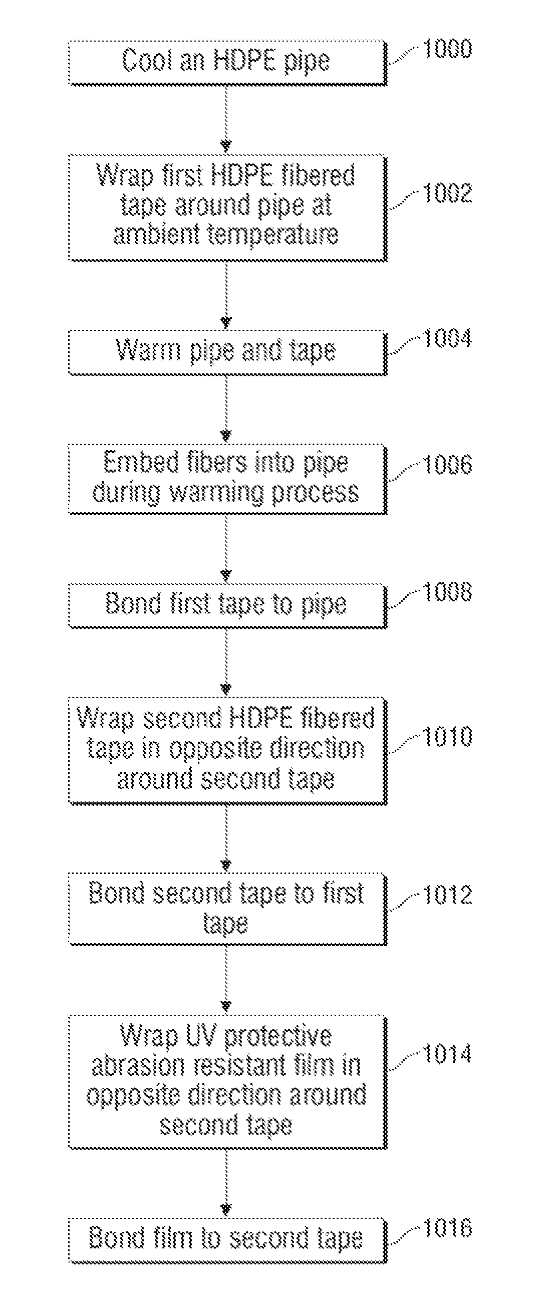
Transporting fluids (or even gasses), such as water and chemicals can be costly and time consuming.
Although technically effective, environmentalists are concerned that fracking fluids may leak from the piping system thus causing damage to the environment.
Consequently, many areas where oil and gas reservoirs exist may not be exploited due to environmental concerns.
However it is not very durable and like the Yelomine™ pipe requires a support system during the fluid transfer.
It is highly durable but costs nearly 3 times more than an aluminum pipe.
The pipes are difficult to transport in rough, uneven or forest terrains.
These pipes are typically buried and then are not reusable.
Consequently, although thick walled HDPE pipes may be more durable then aluminum or Yelomine™ pipes, current thick walled HDPE pipes in industrial use remain very heavy.
Furthermore, coupling these individual thick walled pipes to create the piping system may be slow and burdensome.
The use of the butt fusing system is often time consuming due to its process and the heavy equipment needed to be transported to the installation site for the connection of the pipes.
Consequently, the use of current thick walled HDPE pipes may not be feasible in transporting liquids or gas over a great distance or through rough terrain under high pressure.

Method used


Image

  • Method for manufacturing a reinforced composite pipe
  • Method for manufacturing a reinforced composite pipe
  • Method for manufacturing a reinforced composite pipe

Examples


Embodiment Construction

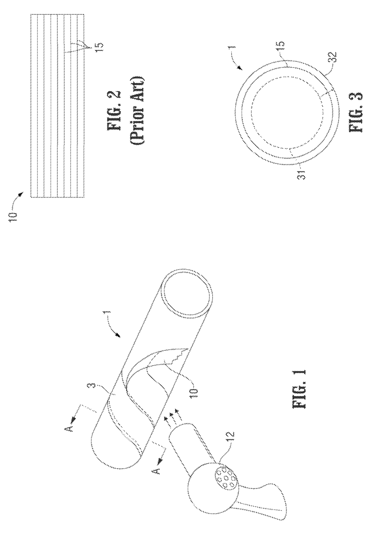
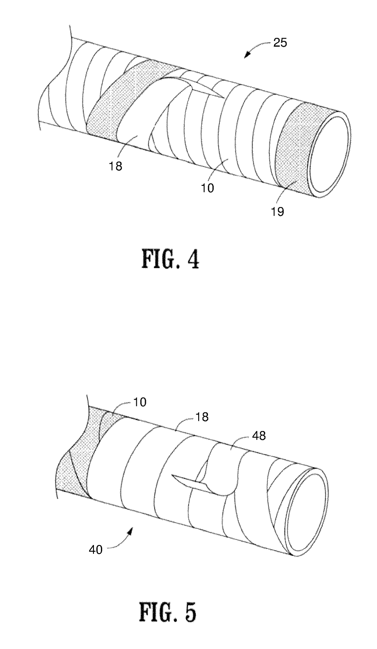
[0025]In FIG. 1, a thermoplastic pipe or tube 1 is shown. In one embodiment according to the present invention, the pipe 1 is a thin walled high density polyethylene pipe. Unlike traditional prior art thick walled thermoplastic (e.g., polyethylene) pipes used for fluid / gas transport for oil and gas applications, the pipe 1 according to the present invention, has a thickness of less than 0.5 inches and preferably less than 0.25 inches. Due to the pipe's thin wall, the pipe 1 is flexible. Furthermore, the thin walled pipe 1 would not be able to withstand the pressures and other factors in oil and gas applications, where in one embodiment fluid pressures exceed 200 PSI. For reinforcement, the pipe 1 is wound with a fiber tape 10. In one embodiment, the tape 10 is made of a similar material to the pipe, such as a high density polyethylene thermoplastic tape. The tape includes continuous fibers 15 that in one embodiment, as shown in FIG. 2, are taut and run along the length of the tape. ...


PUM

PropertyMeasurementUnit
thicknessaaaaaaaaaa
weight ratioaaaaaaaaaa
thicknessaaaaaaaaaa

Abstract

A process for manufacturing pipes using thermoplastic pipe and “tape” (continuous fiber, fully wetted in a similar thermoplastic as the pipe) that embeds the fibers into pipe surface. In one embodiment, an ambient temperature (72 degrees F.) tape is tightly wrapped around the cold pipe in a dry environment (relative humidity below 30). An external heat source is used to heat up the entire length of the pipe causing the thermoplastic to melt and the pipe to expand due to thermal expansion. Since the fibers have less stretch than the thermal expansion of the pipe the fibers will be embedded into the molten layer of the pipe, creating a permanent bond between the fibers and the pipe. A protective film is applied to the pipe. Portions of the tape and film are scraped from the surface of the pipe creating an area where the end of the pipe is coupled to another pipe using an electronic fusion coupler.

Description

BACKGROUND OF THE INVENTION[0001]1. Field of the Invention[0002]This invention relates to a method for manufacturing reinforced thermoplastic pipes used in transporting fluids and gasses.[0003]2. Description of the Related Art[0004]Transporting fluids (or even gasses), such as water and chemicals can be costly and time consuming. For example, in today's energy scarce environment, efficient oil and gas recovery techniques are vital. One means for inducing recovery is using an induced hydraulic fracturing method. “Fracturing fluids” or “pumping fluids” or “fracking fluids” consisting primarily of water and sand are injected under high pressure into the producing formation, creating fissures that allow resources to move freely from rock pores where it is trapped. Chemicals can be added to the water and sand mixture (creating a slickwater) to increase the fluid flow. Fractures provide a conductive path connecting a larger area of the formation to the well, thereby increasing the area fr...

Claims


Application Information

Patent Timeline
Patent Type & Authority Patents(United States)
IPC IPC(8): F16L9/128F16L58/16B29C65/00B29C65/18B29C65/34B29C65/10F16L9/133B29C53/58B29L23/00
CPCF16L9/133B29C53/58B29C65/10B29C65/18B29C65/34B29C66/1122B29C66/1142B29C66/5221B29C66/5229B29C66/5326B29C66/65B29C66/71B29C66/72141B29C66/7392B29C66/861B29C66/8612F16L58/16F16L9/128B29L2023/22B29C66/73921B29C66/7352B29C66/7212B29C53/582B29C65/3468B29K2023/06B29K2023/065B29K2309/08
Inventor TAYLOR, CHRISTOPHER LYNN
Owner COMPOSITE FLUID TRANSFER
Why Eureka
Try Eureka