Dual panel actuator system for jet engines

a technology of actuators and jet engines, applied in the direction of climate sustainability, aircraft power plant components, aircraft power plants, etc., can solve the problems of engine noise and engine inefficiency, add unnecessary complexity and weight, and present a high vibration environment, so as to shorten the actuator stroke and increase the nozzle exhaust area

Active Publication Date: 2018-08-07
PINTO GEOFFREY P
View PDF100 Cites 5 Cited by
  • Summary
  • Abstract
  • Description
  • Claims
  • Application Information

AI Technical Summary

Benefits of technology

[0020]The principal and secondary objects of the invention are to provide an improved jet engine. These and other objects are achieved by a VAFN nozzle that can both translate and tilt about shifting axes in order to increase nozzle exhaust area using a relatively short actuator stroke.

Problems solved by technology

This creates engine noise and engine inefficiency during high thrust and low altitude operations.
Finally, dynamic pressures within the fan duct at high engine power can present a design challenge for aircraft engine designers.
The sleeve is generally a relatively soft structure which slides on loose tracks and thus presents a high vibration environment.
This adds unnecessary complexity and weight while reducing reliability and maintainability.
These prior art designs have only been able to sense nozzle position across the full VAFN stroke by using a dedicated position sensing system connected between the nozzle and the fixed structure where the control system is located, thus incurring a high weight penalty.
This increases weight and makes for poor maintainability and higher complexity resulting in lower reliability.
This increases both weight and aircraft drag.
This yields no weight savings compared to separate actuation systems.
Also, this approach requires transmission of power from the fixed part of the T / R structure to the translating sleeve, then to the VAFN which requires more degrees of freedom resulting in increased weight.
This results in a significant weight penalty by introducing an intermediate pivoting structure between the thrust reverser translating sleeve and fixed nacelle structure.

Method used


Image

  • Dual panel actuator system for jet engines
  • Dual panel actuator system for jet engines
  • Dual panel actuator system for jet engines

Examples


Embodiment Construction

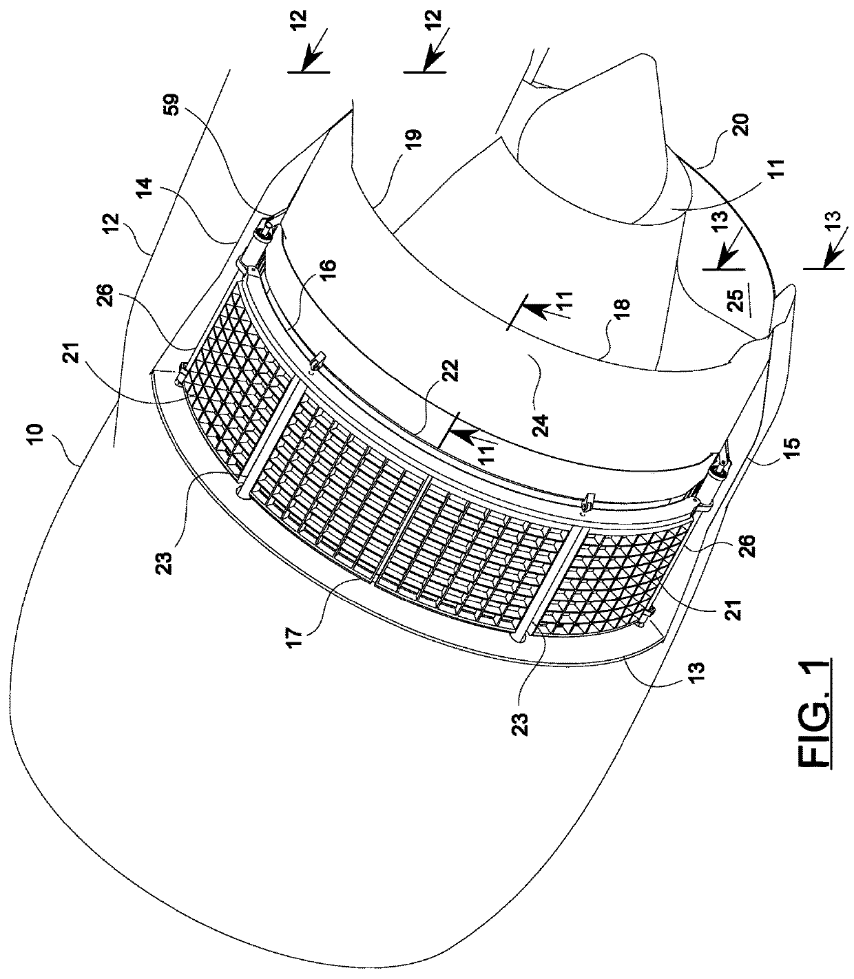
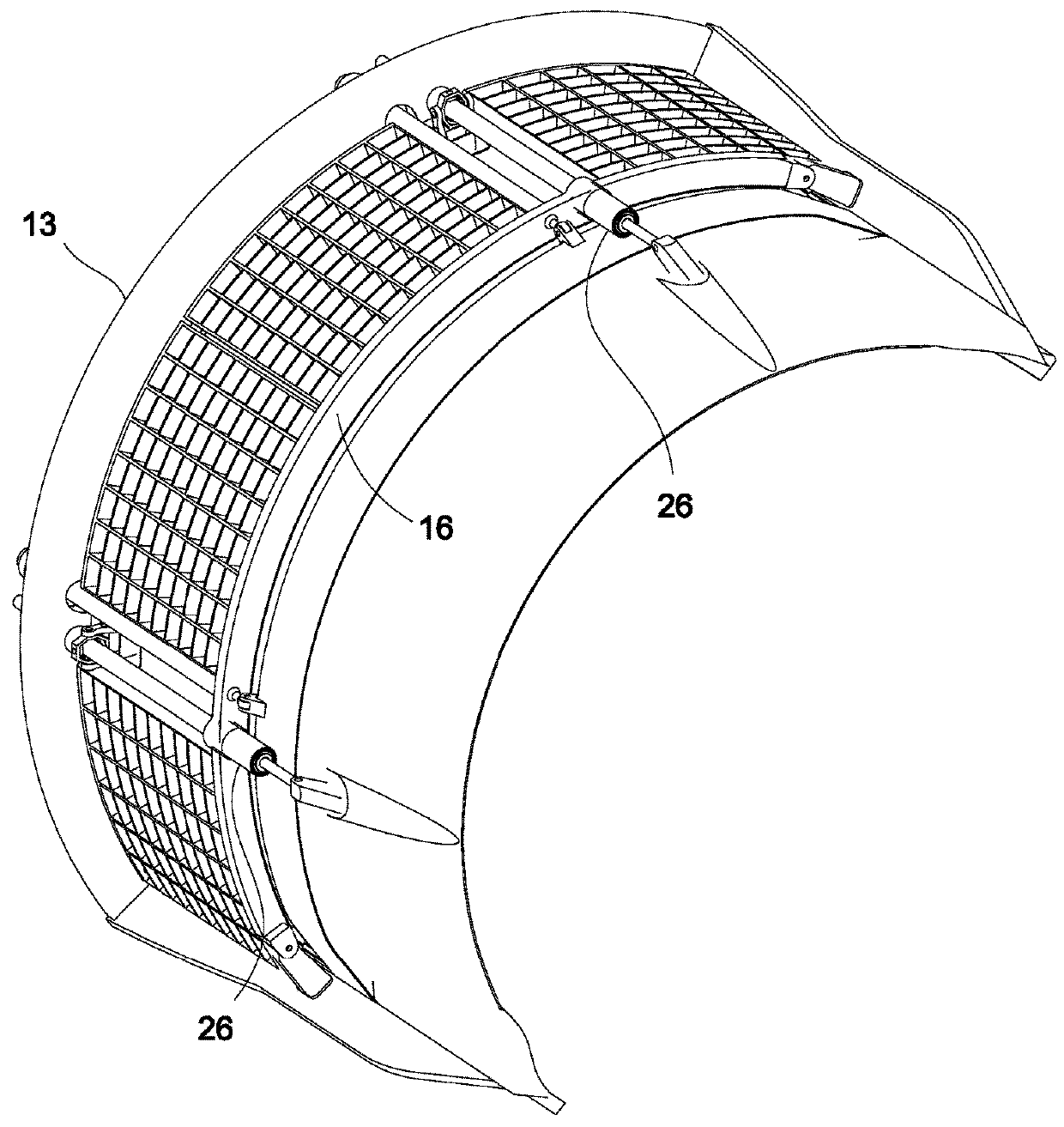
[0128]Referring now to the drawing, there is shown in FIG. 1 the nacelle 10 of an aircraft gas turbine engine 11 supported by a pylon 12 integrating a trust reverser (T / R) 17 including a stationary frame including an annular torque box girder 13, fore-to-aft upper beam 14 and lower beam 15 and a transversal crosstie ring 16. Between the girder and the ring, the T / R further includes a cascade array 21. A semi-circular translatable sleeve 22 enshrouds the cascade array radially inwardly and outwardly. The sleeve can be shifted aftward by actuators 23 to open the T / R. Abaft of the sleeve is a variable area fan nozzle (VAFN) 18 divided into a left half portion 19 and a right half portion 20 by the upper and lower beams. Each half portion has a frusto-conical segment 24 that can be axially translated and tilted to increase or decrease the fan exhaust area 25 by actuators 26.

[0129]It should be noted that both sets of actuators 23, 26 are anchored on components of a stationary structure, n...


PUM


Abstract

An aircraft engine variable area fan nozzle structure disposed abaft a thrust reverser, including a sleeve translatable over a cascade array, comprises two semi cylindrical segments that can be axially translated and radially tilted to enlarge the fan duct exhaust area in order to optimize exhaust pressure and associated noise in high thrust circumstances such as on take-off, and to constrict that area under lower thrust conditions such as cruise. A pair of angularly adjacent segments can be moved by an actuator anchored to the fixed engine framework and independently of the thrust reverser translating sleeve. The tilting movement is imposed by the pivoting links of each segment to carriages that ride in a non-linear trackway secured to a thrust reverser translating sleeve. The actuator can be of a dual concentric type which can independently drive the trust reverser and nozzle segments.

Description

PRIOR APPLICATION[0001]This application is a continuation-in-part of U.S. patent application Ser. No. 14 / 251,316, filed 2014 Apr. 11, which claims the benefit of U.S. Provisional Patent Application Ser. No. 61 / 811,071, filed 2013 Apr. 11, and U.S. Provisional Patent Application Ser. No. 61 / 832,666, filed 2013 Jun. 7, both of which are incorporated herein by reference.FIELD OF THE INVENTION[0002]The instant invention relates to gas turbine aircraft engines, and more particularly to systems for selectively controlling the fan duct bypass flow in order to optimize the engine performance and minimize noise under varying flight conditions.BACKGROUND OF THE INVENTION[0003]An aircraft gas turbine engine thrust reverser (T / R) functions to slow the forward speed of an aircraft either upon landing or during an aborted takeoff. The thrust reverser lessens wear to the landing gear brakes and allows for shorter runway length.[0004]A translating sleeve style T / R features a sleeve structure that r...

Claims


Application Information

Patent Timeline
Patent Type & Authority Patents(United States)
IPC IPC(8): F02K1/06F02K1/09B64D29/06F02K1/08F02K1/12
CPCB64D29/06F02K1/1261F02K1/09F02K1/06F02K1/12Y02T50/60
Inventor PINTO, GEOFFREY P.
Owner PINTO GEOFFREY P
Why Eureka
Try Eureka