Methods and devices for sensing respiration and providing ventilation therapy
What is Al technical title?
Al technical title is built by PatSnap Al team. It summarizes the technical point description of the patent document.
a technology of respiration and sensing devices, applied in medical science, diagnostics, other medical devices, etc., can solve the problems of sensor no longer measuring the respiration of patients, and sensor insufficient measurement of the entire respiratory curv
Active Publication Date: 2018-08-28
BREATHE TECHNOLOGIES INC
View PDF1131 Cites 2 Cited by
Summary
Abstract
Description
Claims
Application Information
AI Technical Summary
This helps you quickly interpret patents by identifying the three key elements:
Problems solved by technology
Method used
Benefits of technology
The present invention is about improving the accuracy and safety of breath sensors used in ventilation gas delivery. It provides a way to protect the sensors from contact with tissue or debris, which can interfere with their readings. This is useful in situations where the sensors are exposed to a patient's breath airflow, as it can help to ensure that the information they provide is accurate and reliable. Overall, the invention provides a better way to manage and monitor a patient's breathing during ventilation.
Problems solved by technology
However, when there is a need or desire to measure the entire respiratory curve in addition to start of inspiration, sensors within the ventilation gas delivery circuit produce inadequate results because the gas being delivered by the ventilator also moves past the sensor.
Thus, the sensor no longer measures the patient's respiration, but rather the gas delivered through the ventilation gas circuit.
In an open ventilation system, or in ventilation systems that augment a patient's spontaneous breathing, sensors within the ventilation gas delivery circuit are inadequate in measuring the entire respiratory curve.
Although an improvement, this approach has the disadvantage that the chest impedance signal is prone to drift, noise and artifacts caused by patient motion and abdominal movement.
However, this has the disadvantage that it is invasive and requires electrodes typically placed in the esophagus to detect the neural activity.
This new breath sensing technology, however, may not be simple or obvious to reduce to practice.
Sensors within the airway of the patient are prone to problems stemming from tissue interaction, patient-to-patient variability, variability within a given patient over time, and a variable physiological environment that can not be controlled.
For example, debris in the airway may collect on the sensors and may cause signal artifacts and disrupt the sensors' ability to accurately and reliably measure the entire breath curve.
Or, the sensor could come into contact with the tracheal wall, which may disrupt the sensors' signal.
Method used
Image
Click on the blue label to locate the original text in one second.
Reading with bidirectional positioning of images and text.
Examples
Embodiment Construction
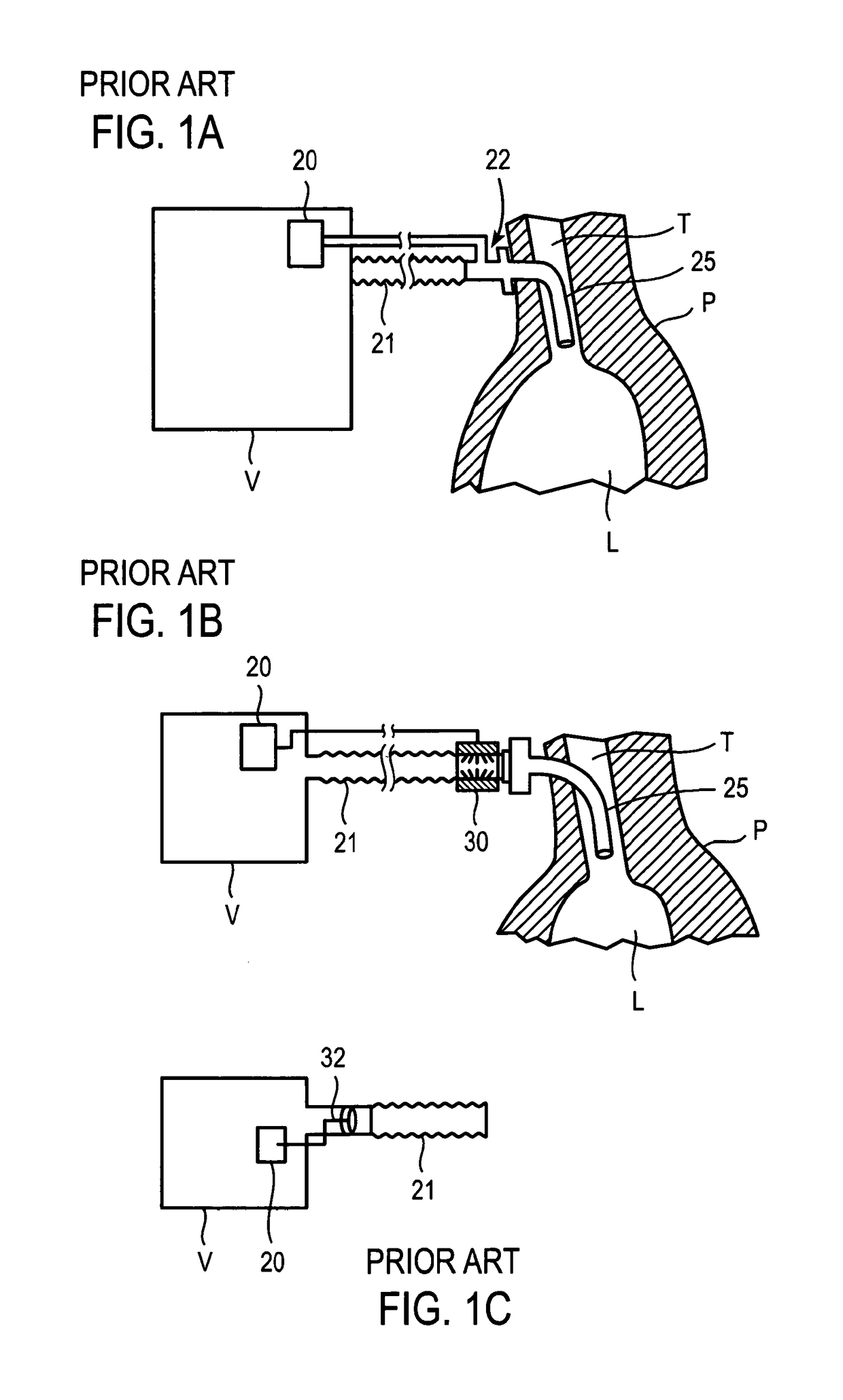
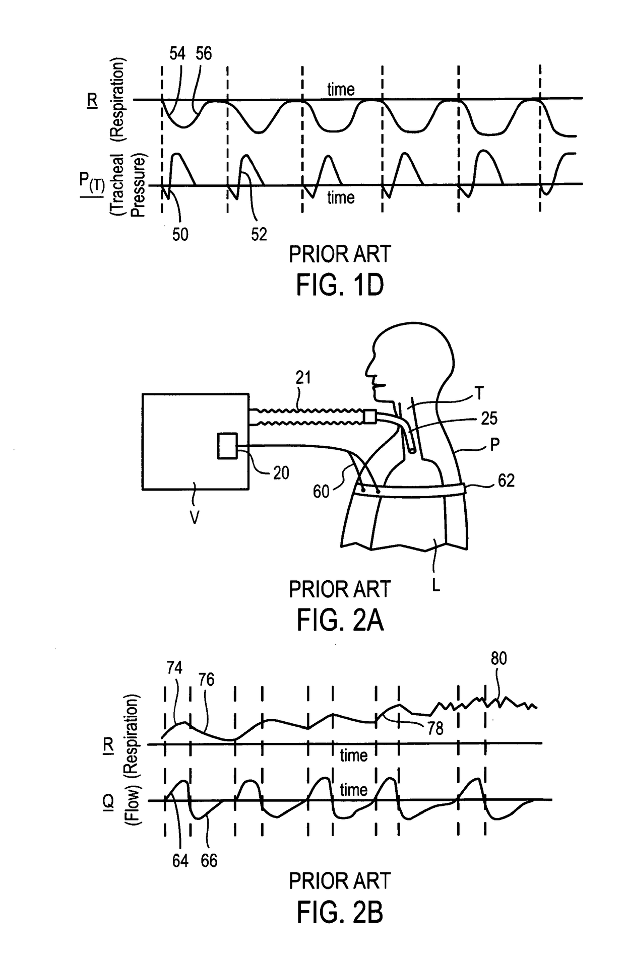
[0063]FIG. 1a shows a prior art ventilator breath detection triggering system where a pressure sensor is located within a ventilation gas delivery circuit 21. A ventilator V may deliver ventilation gas to a patient P through a ventilation gas delivery circuit 21 and a ventilation tube 25. A ventilation circuit pressure tap 22 may be located within the ventilation gas delivery circuit 21. The ventilation circuit pressure tap 22 may sense pressure in the ventilation gas delivery circuit 21. Thus, when the patient P inspires, a negative pressure created in the lung L may be transmitted to the trachea T, and the negative pressure may be detected in the ventilation circuit pressure tap 22. The ventilation circuit pressure tap 22 may be in communication with a ventilator breath delivery control unit 20.
[0064]Alternatively, as shown in FIG. 1b, a flow sensor may be used in place of the pressure sensor. The flow sensor may be an ultrasonic flow sensor 30 or another type of flow sensor. Alte...
PUM
Abstract
Methods and systems are provided for intra-airway breath sensors where intra-airway breath sensors are not located within a ventilation gas delivery circuit, but are exposed to spontaneous respiration airflow from a patient. Furthermore, methods and systems of the present invention may be used to protect an intra-airway breath sensor from contacting tissue or accumulating debris that may impair abilities of the intra-airway breath sensors.
Description
CROSS-REFERENCE TO RELATED APPLICATIONS[0001]This application is a divisional of U.S. patent application Ser. No. 12 / 153,423 which claims priority to U.S. Provisional Patent Application Ser. No. 60 / 924,514, filed May 18, 2007, the disclosure of which is hereby incorporated by reference in its entirety. This application further incorporates by reference in their entireties: U.S. Non-Provisional patent application Ser. No. 10 / 771,803 (U.S. Pat. No. 7,487,778, issued on Feb. 10, 2009), filed Feb. 4, 2004; U.S. Non-Provisional patent application Ser. No. 10 / 870,849 (U.S. Pat. No. 7,588,033, issued on Sep. 15, 2009), filed on Jun. 17, 2004, U.S. Non-Provisional patent application Ser. No. 11 / 523,519 (U.S. Pat. No. 7,533,670 issued on May 19, 2009), filed Sep. 20, 2006 and U.S. Non-Provisional patent application Ser. No. 11 / 523,518, filed Sep. 20, 2006.FIELD OF THE INVENTION[0002]The present invention relates to ventilation therapy for persons suffering from respiratory impairment and bre...
Claims
Application Information
Patent Timeline
Application Date:The date an application was filed.
Publication Date:The date a patent or application was officially published.
First Publication Date:The earliest publication date of a patent with the same application number.
Issue Date:Publication date of the patent grant document.
PCT Entry Date:The Entry date of PCT National Phase.
Estimated Expiry Date:The statutory expiry date of a patent right according to the Patent Law, and it is the longest term of protection that the patent right can achieve without the termination of the patent right due to other reasons(Term extension factor has been taken into account ).
Invalid Date:Actual expiry date is based on effective date or publication date of legal transaction data of invalid patent.