
Energy storage devices and methods for fast charging of energy storage devices at very low temperatures

a technology of energy storage devices and energy storage devices, which is applied in the field of energy storage devices, can solve the problems of user inability to charge, relatively long time, and the inability of charging methods and devices for currently available rechargeable batteries, such as lithium ion batteries, to charge these batteries at low temperatures, so as to minimize the amount of changes and modifications, the effect of fast ra

Active Publication Date: 2018-08-28
OMNITEK PARTNERS LLC
View PDF2 Cites 4 Cited by
  • Summary
  • Abstract
  • Description
  • Claims
  • Application Information

AI Technical Summary

Benefits of technology

The patent aims to make it easy to implement energy storage devices, such as supercapacitors and lithium ion batteries, in different designs. This would require minimal changes to the manufacturing processes for these devices.

Problems solved by technology

As a result, the user may be unable to charge or when the temperature levels are not very low and the supercapacitor is not provided with enough thermal insulation protection, must wait a relatively long time to charge the supercapacitor.
Similarly, charging methods and devices for currently available rechargeable batteries, such as lithium ion batteries, cannot be used for charging these batteries at low temperatures.
However, such low temperatures with regard to lithium ion batteries can be much higher than that discussed above with regard to supercapacitors, such as close to zero degrees C., and still hinder charging, damage the battery and even cause fire hazard because the components of a lithium ion battery are highly sensitive to temperature.
This increase in resistance causes higher losses during charging and discharging of the lithium ion battery.
Low temperature charging passes (relatively high) currents through the components representing the battery electrical-chemical reactions, and is well known to result in so-called lithium plating, which is essentially irreversible, prevents battery charging, and permanently damages the battery.

Method used


Image

  • Energy storage devices and methods for fast charging of energy storage devices at very low temperatures
  • Energy storage devices and methods for fast charging of energy storage devices at very low temperatures
  • Energy storage devices and methods for fast charging of energy storage devices at very low temperatures

Examples


first embodiment

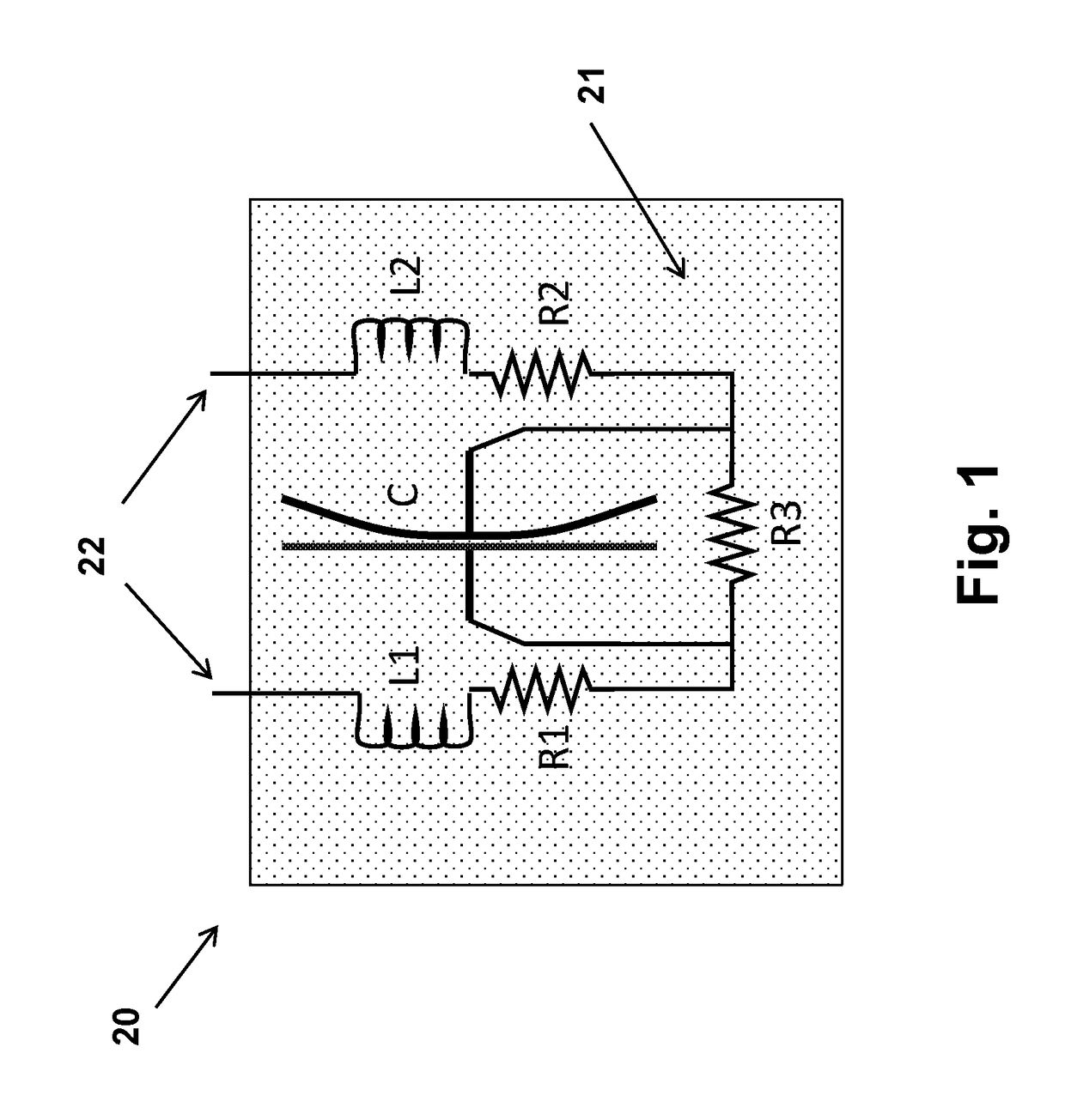
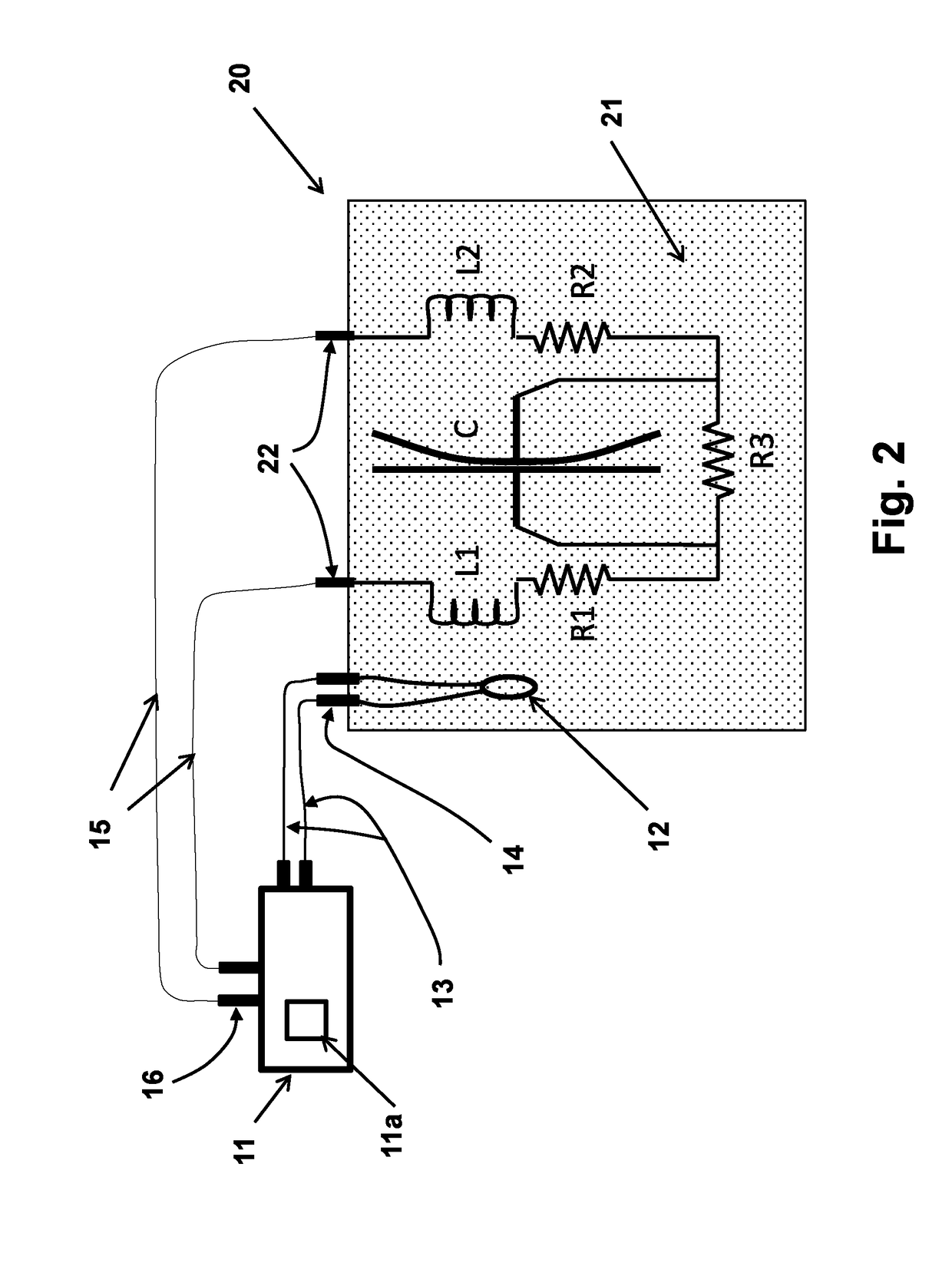
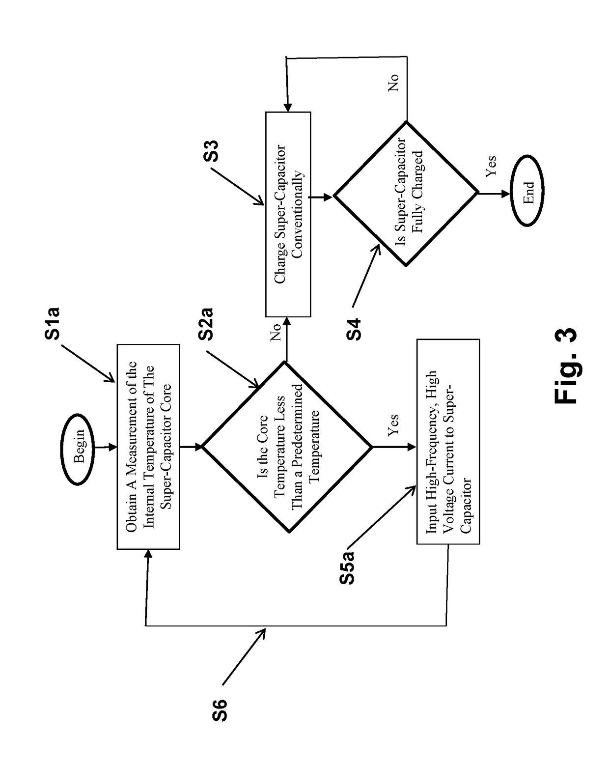
[0052]In the first embodiment shown schematically in FIGS. 2, 3 and 5, a supercapacitor charger unit 11 having an internal processor 11a would first obtain the internal temperature of the supercapacitor core at step S1a or S1b. Such processor comprises a hardware, component such as a PLC or CPU and can include software and a memory storing such software and also storing data such as predetermined values used in the methods described below. In applications, such as munitions in which the munitions has been stored at the ambient temperature, the supercapacitor core temperature may be obtained by measuring the ambient temperature at step S1a and approximating the internal temperature of the supercapacitor core using some function of the ambient temperature, such as equating the ambient temperature to the supercapacitor core temperature. Alternatively, the supercapacitor core temperature can be directly measured by an internal sensor 12 (such as a thermocouple based sensor or other temp...

embodiment 300

[0103]An embodiment 300 of the Lithium ion charging and discharging unit is shown in the block diagram of FIG. 13. Although the unit 300 can be used to solely charge lithium ion batteries at low temperatures, the unit 300 is intended for use as a charging and discharging unit for Lithium ion batteries at all temperatures including at low temperatures.

[0104]It is appreciated here that for Lithium battery charging low temperature is intended to indicate those battery core temperatures at which DC currents (continuous or pulsed or other variations known in the art or the like) causes damage to the battery or that the battery cannot effectively be charged. In the Lithium ion battery discharging process, low temperature is intended to indicate temperatures at which the Lithium ion battery discharge rate is significantly lower than its normal rate. In Lithium ion batteries the latter temperatures are generally lower than those for safe charging of the battery.

[0105]The unit 300 is powered...

embodiment 380

[0114]In the embodiment 380 of FIG. 17, the high frequency AC current producing generator element 306a is powered from an external source 302. External powering of the AC current generator 306a may be necessary in certain situations, for example when the charged battery core is at such a low temperature that cannot provide enough power to the AC current generator 306a or that it cannot provide enough power to raise the core temperature to the required operating temperature in short enough period of time. If such situations are not expected to be encountered, the AC current generator 306a may be powered directly by the Lithium ion battery 301 itself or after an initial external powering period. The embodiment of FIG. 18 illustrates such a discharging control unit 400 in which the AC current generator 306a of the discharging control unit is powered by the battery 301 itself.

[0115]The embodiment 400 shown in FIG. 18 is similar in functionality and design to the embodiment 380 of FIG. 1...


PUM

PropertyMeasurementUnit
capacitanceaaaaaaaaaa
rate voltageaaaaaaaaaa
rated voltageaaaaaaaaaa

Abstract

A method for charging an energy storage device having a core with an electrolyte. The method including: (a) obtaining one or more of a measurement or approximation of a temperature of the electrolyte; (b) determining whether the temperature obtained in step (a) is below a predetermined threshold considered to at least reduce the charging efficiency of the energy storage device; and (c) inputting one or more of a predetermined voltage and current input to terminals of the energy storage device causing internal components of the energy storage device to generate heat if the temperature is determined to be less than the predetermined temperature. Similarly, a method for discharging an energy storage device having an electrolyte is provided.

Description

CROSS REFERENCE TO RELATED APPLICATIONS[0001]This application claims benefit to U.S. Provisional Application No. 62 / 119,003 filed on Feb. 20, 2015; 62 / 168,037 filed on May 29, 2015 and 62 / 189,156 filed on Jul. 6, 2015, all three of which are incorporated herein in their entirety by reference.BACKGROUND[0002]1. Field[0003]The present invention relates generally to energy storage devices, such as supercapacitors and lithium ion batteries, for fast charging and operation at high rate at very low temperatures, more particularly to methods and apparatus for fast charging of energy storage devices, such as supercapacitors and lithium ion batteries and to supercapacitors and lithium ion batteries that are designed to be charged at high rates as well as for high discharge rate operation at very low temperatures. Herein, by very low temperature it is meant the temperatures at which an electrolyte in an interior of such energy storage devices at least hinders charging, such as at temperatures...

Claims


Application Information

Patent Timeline
Patent Type & Authority Patents(United States)
IPC IPC(8): H02J7/00H01G11/14H02J7/34H01G11/54H01M10/637H01M10/0525H01M10/44H01M10/48H01M10/615H01M10/625
CPCH02J7/0052H01G11/54H01M10/0525H01M10/443H01M10/48H01M10/486H01M10/615H01M10/637H02J7/345H01G11/14Y02E70/40H01M10/625H01M2220/20Y02B40/90Y02E60/122Y02E60/13Y02B40/00Y02E60/10Y02T10/70H02J7/00
Inventor RASTEGAR, JAHANGIR SFENG, DAKE
Owner OMNITEK PARTNERS LLC
Learn More