Device for inductively transmitting energy and method for operating a device for inductively transmitting energy

a technology of inductive energy and transmission device, which is applied in the direction of electric vehicle charging technology, charging station, transportation and packaging, etc., to achieve the effect of wide tolerance range, and efficient inductive energy transmission

Inactive Publication Date: 2018-09-04
ROBERT BOSCH GMBH
View PDF16 Cites 1 Cited by
  • Summary
  • Abstract
  • Description
  • Claims
  • Application Information

AI Technical Summary

Benefits of technology

[0009]The present invention is based on the idea of extending a system for inductive energy transmission to the secondary side in such a way that an additional degree of freedom is provided in the regulation that is used to optimize the respective working point. An additional idling state is permitted on the secondary side for this purpose, in that the two lower diodes of the rectifier are replaced by active switches. Through a targeted utilization of this newly introduced idling state, the efficiency of the inductive energy transmission can, for example, be increased at a large number of working points.
[0010]The inductive energy transmission can, moreover, also be operated under unfavorable coupling factors such that a maximum magnetic field strength is not exceeded in the air gap between the primary coil and the secondary coil. Hazards that can arise from excessively high magnetic field strengths, such as through heating up external metal objects, can thus be avoided.
[0011]Through the targeted utilization of the additional idling state on the secondary side, an inductive energy transmission is permitted over a very wide tolerance range of the coupling factor. In particular, even at coupling factors that in a conventional system would only permit a very poor inductive energy transmission or none at all, an efficient inductive energy transmission can thus nevertheless be carried out. The efficiency can also be crucially improved when operating at otherwise unfavorable working points, such as operation under partial load.
[0012]The inductive energy transmission according to the invention moreover also permits an additional protective function through the targeted and lasting short-circuiting of the secondary side in the event of a fault. An unacceptably high rise in the primary current that would occur in the presence of uncontrolled shedding of load on the secondary side can, for example, be prevented in this way.
[0014]According to a further embodiment, the switching arrangement comprises at least one semiconductor switch. Preferably the semiconductor switch is a MOSFET or an IGBT. Such semiconductor switches permit a reliable, fast and low-loss switching of the switching arrangement over a long period.

Problems solved by technology

The inductive energy transmission can, moreover, also be operated under unfavorable coupling factors such that a maximum magnetic field strength is not exceeded in the air gap between the primary coil and the secondary coil.

Method used


Image

  • Device for inductively transmitting energy and method for operating a device for inductively transmitting energy
  • Device for inductively transmitting energy and method for operating a device for inductively transmitting energy
  • Device for inductively transmitting energy and method for operating a device for inductively transmitting energy

Examples


Embodiment Construction

[0029]Even though the present invention is described below preferably with reference to an electric energy transmission for charging an electric vehicle, the inductive energy transmission according to the invention is not restricted to this application. It is also further possible to extend the energy transmission according to the invention to any other desired application. Furthermore the output voltage provided at the output of the device described can, in addition to charging a battery, also be used for any other desired application.

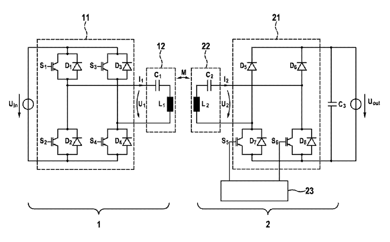
[0030]FIG. 1 shows a schematic illustration of a circuit arrangement for an inductive energy transmission, as is the basis for an embodiment of the present invention. The circuit arrangement comprises a primary side 1 and a secondary side 2. The primary side 1 is fed from a DC voltage source 10. It is also alternatively possible for feed to be provided from an alternating voltage source with subsequent rectification. The primary side 1 can, moreover, ...


PUM

PropertyMeasurementUnit
electric voltageaaaaaaaaaa
magnetic fieldaaaaaaaaaa
alternating electric voltageaaaaaaaaaa

Abstract

The invention relates to inductive energy transmission from a primary coil (12) to a secondary coil (22) having an additional operating state. By means of this two-sided regulation, a primary-side and secondary-side control of the power electronics is performed in accordance with a predetermined operational strategy. Thus, even in the case of unfavorable coupling factors, for example, the efficiency of the inductive energy transmission can be increased, the magnetic field in the air gap between the primary coil (12) and the secondary coil (22) can be minimized, and the inductive energy transmission can be optimized. This optimized operational strategy is enabled by means of a newly introduced idle state, which permits periodic short-circuiting of the secondary side by means of switches on the secondary side (S5, S6) of the inductive energy transmission system. The invention is preferably used in the charging of the battery of an electric vehicle (4), but other applications are also possible.

Description

BACKGROUND OF THE INVENTION[0001]The present invention relates to a device for inductive energy transmission, and to a method for operating a device for inductive energy transmission.[0002]Electric vehicles and plug-in hybrid vehicles, which are driven entirely or at least partially by means of electric motors, are known. The electrical energy here for driving the electric motor is provided by an electric energy store, for example a traction battery. Different approaches are taken to charging this energy store.[0003]It is, for example, possible to connect the electric vehicle conductively to a charging station by means of a suitable charging cable. A user must establish an electrical connection between the electric vehicle and the charging station for this purpose. This can be found to be uncomfortable, in particular under bad weather conditions such as rain. As a result of the highly restricted electrical range of electric and plug-in hybrid vehicles, this cable connection must, mo...

Claims


Application Information

Patent Timeline
Patent Type & Authority Patents(United States)
IPC IPC(8): H01F27/42B60L11/18H02J50/12H02J5/00H02J7/02H02J50/10
CPCB60L11/182H02J5/005H02J7/025H02J50/10H02J50/12Y02T90/14Y02T10/7005Y02T10/7072Y02T90/122B60L53/122B60L53/126H02J7/00712Y02T10/70B60L53/12B60Y2200/91Y02T90/12
Inventor PLUM, THOMASDIEKHANS, TOBIAS
Owner ROBERT BOSCH GMBH
Why Eureka
Try Eureka