
Petri net-based optimal one-wafer cyclic scheduling of treelike hybrid multi-cluster tools

a hybrid multi-cluster tool and scheduling technology, applied in the direction of instrumentation, programme control, total factory control, etc., can solve the problems of difficult scheduling, complex multi-cluster tool, and difficult evaluation of performan

Inactive Publication Date: 2018-09-11
MACAU UNIV OF SCI & TECH
View PDF31 Cites 0 Cited by
  • Summary
  • Abstract
  • Description
  • Claims
  • Application Information

AI Technical Summary

Benefits of technology

The present invention provides a computer-implemented method for scheduling a treelike hybrid K-cluster tool to generate a one-wafer cyclic schedule. The method involves generating a part of the schedule for a section of the K-cluster tool by performing a generating algorithm based on a given cycle time and a value of θ. The algorithm takes into account various conditions such as the number of wafers and the number of single-cluster tools. The method can be used to efficiently schedule the K-cluster tool and improve production efficiency.

Problems solved by technology

However, it is hard to evaluate its performance.
Structurally, a treelike hybrid multi-cluster tool is much more complex than a linear multi-cluster tool and thus it is more challenging to schedule.

Method used


Image

  • Petri net-based optimal one-wafer cyclic scheduling of treelike hybrid multi-cluster tools
  • Petri net-based optimal one-wafer cyclic scheduling of treelike hybrid multi-cluster tools
  • Petri net-based optimal one-wafer cyclic scheduling of treelike hybrid multi-cluster tools

Examples


example 1

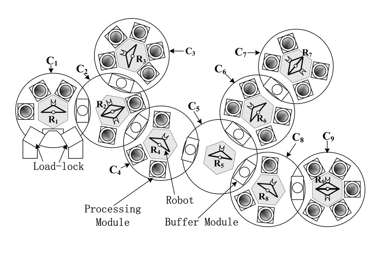
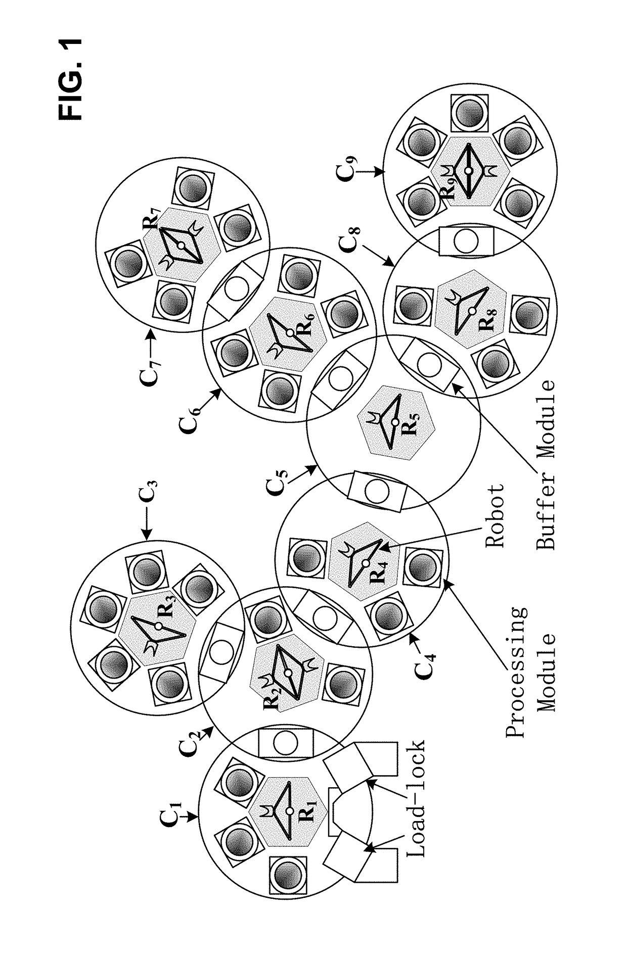
[0210]It is a treelike hybrid 3-cluster tool, where C1 is a fork tool and its adjacent downstream tools are C2 and C3. Furthermore, C2 and C3 are single-arm tools, and C1 is a dual-arm tool. Their activity times are as follows. For C1, (α10, α11, α12, α13, λ1, μ1)=(0, 77, 0, 0, 23, 1); for C2, (α20, α21, α22, λ2, μ2)=(0, 75, 79, 4, 1); and for C3, (α30, α31, α32, λ3, μ3)=(0, 71, 69, 6, 1).

[0211]For C1, one has ξ10=23 s, ξ11=100 s, ξ12=23 s, ξ13=23 s, ψ11=(n[1]+1)×(λ1+μ1)=4×24=96 s, and Π1=100 s. For C2, one has ξ20=19 s, ξ21=94 s, ξ22=98 s, ψ21=2(n[2]+1)×(λ2+μ2)=6×5=30 s and Π2=98 s. For C3, one has ξ30=27 s, ξ31=98 s, ξ32=96 s, ψ31=2(n[3]+1)×(λ3+μ3)=6×7=42 s and Π3=98 s. Since all the individual tools are process-bound, this 3-cluster tool is process-dominant, and one lets Θ=π1=π2=π3=Π=Π1=100 s. By the algorithm provided in [Yang, et al., 2015], the robots' waiting time is set as ω20=6 s, ω21=2 s, and ω22=Π−ψ21−ω20−ω21=100−30−6−2=62 s; ω30=2 s, ω31=4 s, and ω32=Π−ψ31−ω30−ω31=100−42...

example 2

[0213]It is from [Yang, et al., 2015]. A treelike hybrid 5-cluster tool with C2 be a fork tool, and its adjacent downstream tools are C3 and C5. The tool C4 is the downstream tool of C3, and C2 is the downstream tool of C1. Furthermore, C1 is a dual-arm tool and the others are single-arm tools. Their activity time is as follows: for C1, one has (α10, α11, λ1, μ1)=(0, 61.5, 0, 28.5, 0.5); for C2, one has (α20, α21, α22, λ2, μ2)=(0, 0, 0, 10, 1); for C3, one has (α30, α31, α32, α33, λ3, μ3)=(0, 56, 0, 58, 7, 1); for C4, one has (α40, α41, α42, α43, λ4, μ4)=(0, 56, 66, 65, 5, 1); and for C5, one has (α50, α51, α52, λ5, μ5)=(0, 48, 50, 6, 1).

[0214]From [Yang, et al., 2015], the lower bound of cycle time of the system is Θ=Π=90 s. With Θ=Π=90 s, the robot waiting time is set as follows. For C4, ω40=11 s, ω41=1 s, ω42=2 s, and ω43=28 s are set. For C5, ω50=15 s, ω51=13 s, and ω52=20 s are set. For C3, ω31=8 s, ω30=3 s, ω32=1 s, and ω33=14 s are set. For C2, ω20=2 s, ω21=0, and ω22=22 s ar...


PUM


Abstract

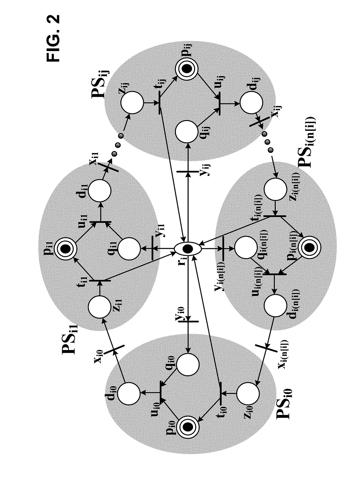
Since single and dual-arm tools behave differently, it is difficult to coordinate their activities in a hybrid multi-cluster tool that is composed of both single- and dual-arm tools. Aiming at finding an optimal one-wafer cyclic schedule for a treelike hybrid multi-cluster tool whose bottleneck tool is process-bound, the present work extends a resource-oriented Petri net to model such system. By the developed Petri net model, to find a one-wafer cyclic schedule is to determine robot waiting times. By doing so, it is shown that, for any treelike hybrid multi-cluster tool whose bottleneck tool is process-bound, there is always a one-wafer cyclic schedule. Then, computationally efficient algorithms are developed to obtain the minimal cycle time and the optimal one-wafer cyclic schedule. Examples are given to illustrate the developed method.

Description

CROSS-REFERENCE TO RELATED APPLICATIONS[0001]This application claims the benefit of U.S. Provisional Patent Application No. 62 / 221,038, filed on Sep. 20, 2015, which is incorporated by reference herein in its entirety.LIST OF ABBREVIATIONS[0002]BM buffer module[0003]FP fundamental period[0004]EST extended sub-tree[0005]LB lower bound[0006]O2CS optimal one-wafer cyclic schedule[0007]OSLB one-wafer cyclic schedule achieving the LB of cycle time[0008]PM process module[0009]PN Petri net[0010]ST sub-treeBACKGROUNDField of the Invention[0011]The present invention generally relates to scheduling a treelike hybrid multi-cluster tool. In particular, the present invention relates to a method for generating an optimal one-wafer cyclic schedule with minimal cycle time for this multi-cluster tool when no one-wafer cyclic schedule that achieves a LB of cycle time exists.LIST OF REFERENCES[0012]There follows a list of references that are occasionally cited in the specification. Each of the disclos...

Claims


Application Information

Patent Timeline
Patent Type & Authority Patents(United States)
IPC IPC(8): G05B19/41G05B19/418
CPCG05B19/4187G05B2219/31429Y10S901/41Y02P90/205Y10S901/02G05B2219/45032Y02P90/02
Inventor WU, NAIQIYANG, FAJUNQIAO, YANZHOU, MENGCHU
Owner MACAU UNIV OF SCI & TECH
Learn More