Soldering device

a technology of a soldering device and a nut is applied in the direction of auxillary welding devices, soldering apparatus, gearing, etc., which can solve the problems of difficult movement of the nut, difficult to adjust the width of the rail, and difficulty in removing the nut, so as to facilitate the change (adjustment) of the fixed position of the nut and the effect of smooth rotation

Active Publication Date: 2018-09-11
SENJU METAL IND CO LTD
View PDF54 Cites 0 Cited by
  • Summary
  • Abstract
  • Description
  • Claims
  • Application Information

AI Technical Summary

Benefits of technology

[0014]By the nut used for this invention, it is possible to strip the adhered matter by a function of the non-meshing part even when the adhered matter is fixed to the screw shaft screwed onto the nut. Since the non-meshing part strips off or scraps the adhered matter without fixing the matter stripped by the nut to another screw shaft (valley of screw) again, it stops the prevention of the revolution of the screw shaft by the stripped adhered matter (scrapped matter) so that the screw shaft smoothly rotates. As a result thereof, it is possible to change (adjust) a fixed position of the nut easier that the conventional case.
[0015]By the soldering device according to the invention, since any flux fumes which are adhered and solidified to the members (screw shaft and nut) for adjusting a width between the rails to match a size of a substrate in the soldering device are removed while they are scrapped, a forward or backward movement of the nut to the screw shaft becomes easy so that it is easily possible to change the fixed position of the nut. Accordingly, it is easily possible to remove the flux adhered to the members (screw shaft and nut) for adjusting the width between the rails to match the size of the substrate.
[0016]When applying the nut used for the invention and the screw shaft screwed onto the nut to a reflow device, it is easily possible to adjust a width between the rails for conveying the printed circuit board to match the size of the board. Since the adhered flux is able to be easily removed, it is possible to reduce time and costs required for maintenance of the soldering device.

Problems solved by technology

Any problems occur when a large amount of solid fumes, so-called fume solids is applied to each component constituting the reflow furnace.
Since the solidified flux fumes are hard to be removed and are strongly adhered, it is not easily possible to remove them by revolving the screw shaft.
Accordingly, a movement of the nut is difficult so that it is very difficult to adjust the width of the rails.
The flux components heated by the solder layer, however, evaporate, so that the problem in the above-mentioned reflow device also occurs in the jet soldering device.
In addition, even when any adhered matters are fixed to at least any one of the nut and the screw shaft other than the soldering device, any similar problems occur such that these fixed matters are not easily removed by the revolving the screw shaft.

Method used


Image

  • Soldering device
  • Soldering device
  • Soldering device

Examples


first embodiment

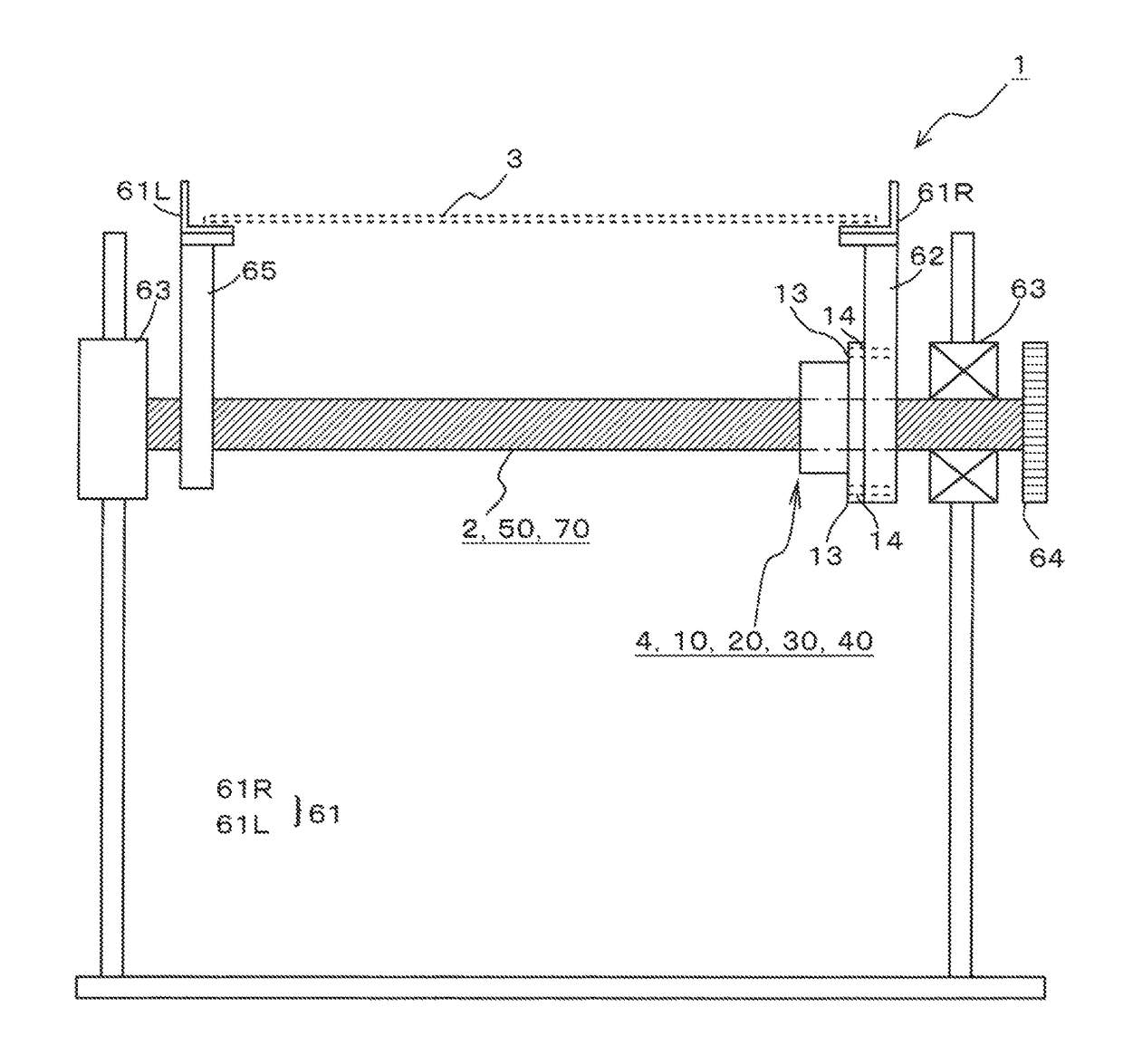
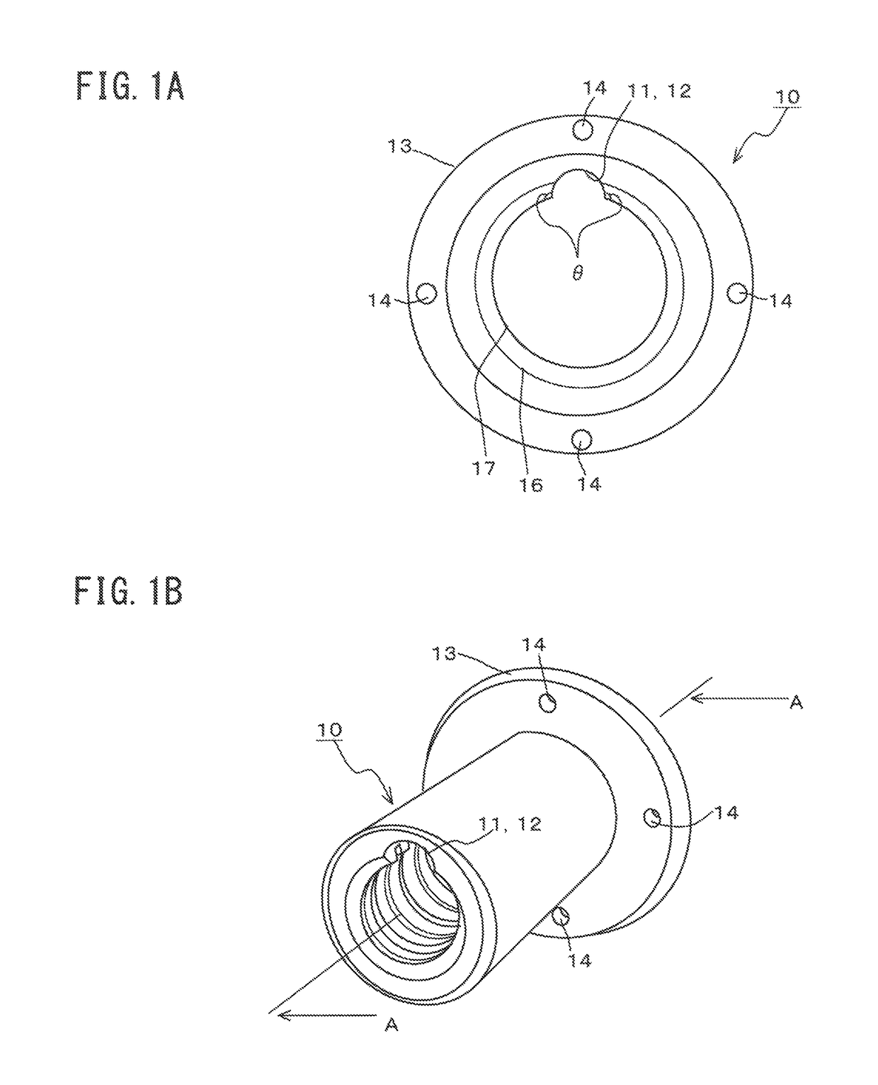
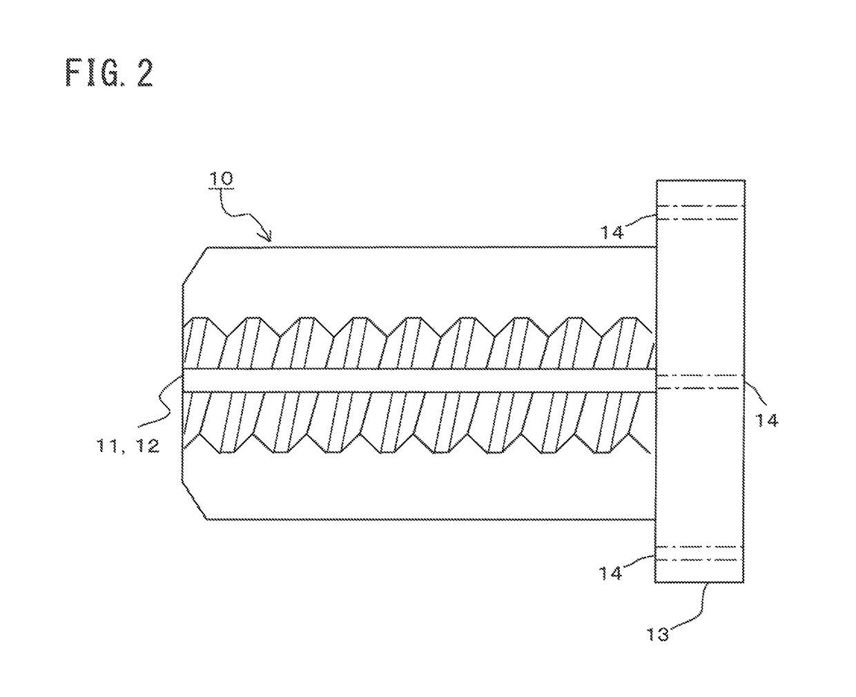
[0034]A configuration example and a variation example of a nut 10 will be described with reference FIGS. 1A through 3B. The nut 10 shown in FIGS. 1A and 1B screws on to a screw shaft 2 having a predetermined length (see FIG. 4) and is able to change the fixed position of the nut 10 to the screw shaft 2. In FIG. 1A, a narrow line circle indicates a valley 16 of screw in the nut 10. A bold line circle indicates a screw thread 17 of the nut 10.

[0035]The nut 10 shown in FIG. 1B includes one non-meshing part 11 which does not mesh with the screw shaft 2 and a flange portion 13 for connecting another member at a screw head of the nut 10. The non-meshing part 11 includes a notch 12 that is formed by cutting off a part of the screw head of the nut 10 in an arc-like shape. The flange portion 13 contains four connecting holes 14 in this embodiment for allowing it to be connected to another member by screws or the like.

[0036]A shape of the notch 12 is not limited to an arc-like shape. It is pr...

second embodiment

[0049]The following will describe a configuration example of the nut 20 as the embodiment with reference to FIGS. 6A and 6B.

[0050]The nut 20 screws on to the screw shaft 2 having a predetermined length (see FIG. 4) and is able to change the fixed position of the nut 20 to the screw shaft 2. The nut 20 includes two non-meshing parts 21 which do not mesh with the screw shaft 2 and a flange portion 23 for connecting another member at a screw head of the nut 20. The flange portion 23 contains connecting holes 24 for allowing it to be connected to another member by screws or the like.

[0051]The non-meshing part 21 is composed of notches 22 that are formed by cutting off the screw threads of the nut 20 in an arc-like shape for every 180 degrees. Each of the notches 22 are arranged parallel to a movement direction of the nut 20 to the screw shaft 2 to extend from a screw end of the nut 20 across at least three screw threads. A number of the screw threads to be cut off may have a sufficient ...

third embodiment

[0058]The following will describe a configuration example of the nut 30 as the embodiment with reference to FIGS. 7A and 7B. The nut 30 screws on to the screw shaft 2 having a predetermined length (see FIG. 4) and is able to change the fixed position of the nut 30 to the screw shaft 2. The nut 30 includes two non-meshing parts 31 which do not mesh with the screw shaft 2 and a flange portion 33 for connecting another member at a screw head of the nut 30. The flange portion 33 contains connecting holes 34 for allowing it to be connected to another member by screws or the like.

[0059]The non-meshing parts 31 include the notches 32 formed by piecing circular holes on the screw thread. The notches 32 are formed on a radial direction of the nut 30.

[0060]Two notches 32 are symmetrically arranged on a radial direction of the nut 30. The notches 32 preferably pass through the nut 30 but the depth thereof may be a sufficient depth to strip off the fixed matters 6 (see FIGS. 5A and 5B) fixed to...


PUM

PropertyMeasurementUnit
angleaaaaaaaaaa
angleaaaaaaaaaa
sizeaaaaaaaaaa

Abstract

Provided are a nut, an attachment for nut and a screw shaft, which are fitted to a coating material coating device or a soldering device and can change a fixed position of the nut easier than that of a convention example even if any adhered matters generated when each device is used for a long time are fixed, and a soldering device using the same. The nut 10 screws on to the screw shaft 2 having a predetermined length. The nut 10 is provided with a non-meshing part 11 composed of a notch 12 that is formed parallel to a movement direction thereof by cutting off screw threads and a flange portion 13, which has connecting holes 14 for connecting another member. Under such a configuration, by forward and / or backward movement of the nut 10, the notch 12 functions as if it scraps the fixed matters 6.

Description

CROSS-REFERENCE TO RELATED APPLICATIONS[0001]This application is the United States national phase of International Application No. PCT / JP2015 / 078460 filed Oct. 7, 2015, and claims priority to Japanese Patent Application No. 2014-208349 filed Oct. 9, 2014, the disclosures of which are hereby incorporated in their entirety by reference.TECHNICAL FIELD[0002]The present invention relates to a soldering device or the like such as a reflow device, a jet soldering device or the like in which flux is utilized when mounting electronic components on a printed circuit board. It specifically relates to a soldering device using a nut, which does not hinder a screw shaft from revolving even when a part of the flux evaporated by the soldering is adhered and fixed to the screw shaft or the like.BACKGROUND TECHNOLOGY[0003]When soldering electronic components on a printed circuit board, a soldering device such as a reflow device, a jet soldering device or the like has been generally used. For example...

Claims


Application Information

Patent Timeline
Patent Type & Authority Patents(United States)
IPC IPC(8): B23K37/00B23Q1/26B23K3/06B23K3/08B23K1/08F16H25/24H05K3/34
CPCH05K3/34B23K1/08B23K3/06F16H25/24B23K3/08B23Q1/265B23K3/0676F16H25/20F16H25/2418B23K1/0016B23K2101/36
Inventor SUGIHARA, TAKASHITAGUCHIHIYAMA, TSUTOMU
Owner SENJU METAL IND CO LTD
Why Eureka
Try Eureka