Centrifugal pump

a centrifugal pump and centrifugal pump technology, applied in the direction of machines/engines, non-positive displacement fluid engines, liquid fuel engine components, etc., can solve the problems of premature wear or failure of the pump, thermal stresses within the centrifugal pump, etc., to reduce the variety of components and reduce the thermal stress within the pump

Inactive Publication Date: 2018-09-25
GRUNDFOS HLDG
View PDF21 Cites 3 Cited by
  • Summary
  • Abstract
  • Description
  • Claims
  • Application Information

AI Technical Summary

Benefits of technology

[0007]Against this background, it is an object of the invention to provide a multistage centrifugal pump which on the one hand avoids, or at the minimum reduces thermal stresses within the pump, and on the other hand the variety of components is reduced with the construction of construction series having a different stage number.
[0010]Thereby, in the simplest form, the outer casing can have a cylindrical shape and be radially clamped in the head part and foot part or be firmly connected to the head part or foot part via essentially radially arranged screws. These screws can for example be led through corresponding bores which are arranged distributed over the periphery of the outer casing at its end, and be fixed in the head part or foot part. Preferably however, the outer casing at its axial ends is designed in a radially widened manner, since a fastening which is simple and effective to the same extent is possible by way of this, and on the other hand the assembly is very simple, since a funnel-like receiver results, which permits a simple assembly on the outer periphery of the pump stages.
[0012]Thereby, the flange connection is preferably designed such that the connection between the outer casing and the head part or foot part is effected with a non-positive as well as positive fit. Thereby, the positive fit provides a high security against a failure of the connection, whereas the non-positive fit ensures that the forces are introduced uniformly over the periphery and as a rule no further securing means preventing a release of the connection need to be provided.
[0018]Alternatively, the flange can also be formed of several flange parts which are formed from sheet metal and which in the region of recesses, thus where the screw fastening is effected, are reinforced by support parts preferably likewise consisting of sheet metal. These sheet metal parts including the support parts are advantageously designed as punched parts and are connected to one another by welding for example, thus can be manufactured particularly inexpensively on a large scale and are preferably manufactured of stainless steel.

Problems solved by technology

The latter fact leads to the fact that the temperature of the screws can differ significantly from that of the delivery fluid and thus also that of the spiral housing or of the outer casing, which leads to thermal stresses within the centrifugal pump.
Such thermal stresses can also lead to premature wear or failure of the pump.
A further disadvantage of this construction type is the fact that not only the shaft and, as the case may be, the outer casing must be provided in different lengths depending on the number of pump stages, but also that the screws connecting the head part and foot part must be provided in different lengths, in order depending on the number of pump stages, to connect the head part and foot part amid the inclusion of the pump stages.

Method used


Image

  • Centrifugal pump
  • Centrifugal pump
  • Centrifugal pump

Examples


Embodiment Construction

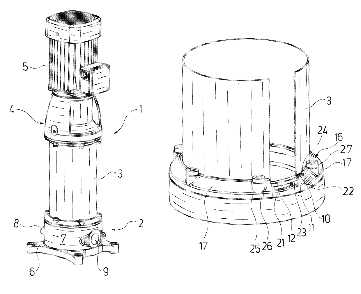
[0034]With regard to the represented centrifugal pump 1, it is the case of a multi-stage inline pump. The centrifugal pump 1 is envisaged for upright operation and it comprises a foot part 2, to which an outer casing 3 connects to the top, the upper end of said outer casing being received by a head part 4 which simultaneously forms a motor base for the electrical drive motor 5 arranged thereabove. The construction of the pump represented in FIG. 1 corresponds to the basic construction of such vertical, multistage high pressure centrifugal pumps of the inline construction manner, as are manufactured and offered for example by the company Grundfos under the type description CR or CRE.

[0035]The foot part 2 consisting of cast metal comprises a lower plate 6 which is formed with this as one piece, forms the actual foot of the centrifugal pump 1 and with which the centrifugal pump 1 stands on the base and can be screw-fastened to the base via bores located in the plate 6. The foot part 2 ...


PUM


Abstract

The centrifugal pump (1) includes several pump stages which are arranged axially between a head part (4) and a foot part (2). An outer casing (3) peripherally surrounds the pump stages. An axial end of the outer casing (3) is fastened on the head part and the other axial end of the outer casing (3) is fastened on the foot part. A mechanical connection between the head part (4) and the foot part (2) is formed by the outer casing (3).

Description

CROSS REFERENCE TO RELATED APPLICATIONS[0001]This application is a United States National Phase Application of International Application PCT / EP2014 / 059977 filed May 15, 2014 and claims the benefit of priority under 35 U.S.C. § 119 of European Patent Application 13173439.4 filed Jun. 24, 2013 the entire contents of which are incorporated herein by reference.FIELD OF THE INVENTION[0002]The invention relates to a centrifugal pump with several pump stages.BACKGROUND OF THE INVENTION[0003]Multi-stage centrifugal pumps are known, with which several pump stages, in each case consisting of a pump impeller and a spiral housing which surrounds this, are arranged between a head part and a foot part, wherein the impellers are arranged on a common shaft. Thereby, the head part and foot part amid the inclusion of the pump stages are connected to one another via outer-lying tie rods in the form of screws.[0004]Such a centrifugal pump typically comprises four screws, which run on the outside along ...

Claims


Application Information

Patent Timeline
Patent Type & Authority Patents(United States)
IPC IPC(8): F04D29/42F04D17/08F04D29/22F04D29/28F01D1/06F04D29/62F04D1/06
CPCF04D29/628F04D1/06F04D17/08F04D29/22F04D29/624F04D29/4206F04D29/426F04D29/4266F04D29/28
Inventor MIKKELSEN, STEENLUNDSTED POULSEN, BRIAN
Owner GRUNDFOS HLDG
Why Eureka
Try Eureka