

Light sheet microscopy using meso-optical elements
a technology of optical elements and light sheets, applied in the direction of optical elements, fluorescence/phosphorescence, instruments, etc., can solve the problems of widening the effective thickness of the analyzable optical layer, generating concentric sted illumination by the low rayleigh length of the beam, and undesirable secondary maxima
- Summary
- Abstract
- Description
- Claims
- Application Information
AI Technical Summary
Benefits of technology
Problems solved by technology
Method used
Image

Examples
Embodiment Construction
[0027]The invention will be described in more detail through the following embodiments.
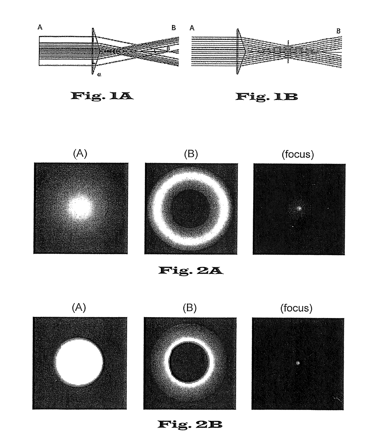
[0028]FIG. 1 shows the beam trajectory and thus schematically sketches by means of the line thickness the transverse intensity profile when a light beam goes through a meso-optical element at point A, the focus point and at point B the transverse intensity profile is recorded. FIG. 1A shows a laser beam with transverse Gaussian profile (Gaussian beam) going through an Axicon lens. FIG. 1B shows a laser beam with transverse flattened Gaussian profile (FGB) going through an Axicon lens.
[0029]FIG. 2 shows schematically the intensity distributions of the light beams according to FIGS. 1A and 1B at the aperture of the Axicon lens (A) and at some distance from the focus (B) as well as at the focus point (focus) itself. FIG. 2A shows the intensity distribution of a Gaussian laser beam (FIG. 1A). FIG. 2B shows the corresponding intensity distributions of a flattened Gaussian laser beam (FIG. 1B).
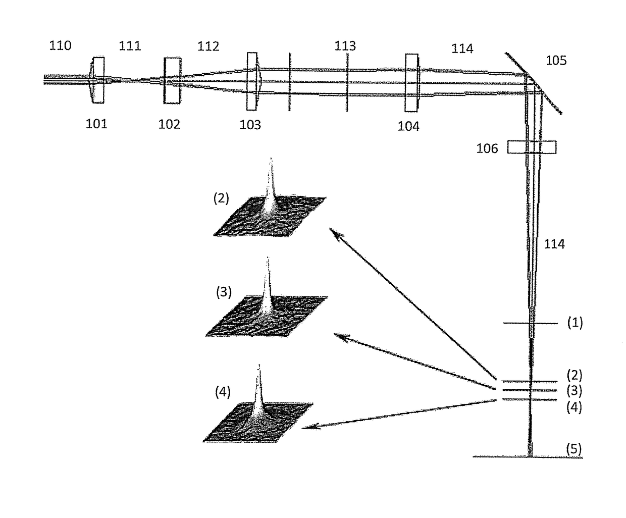
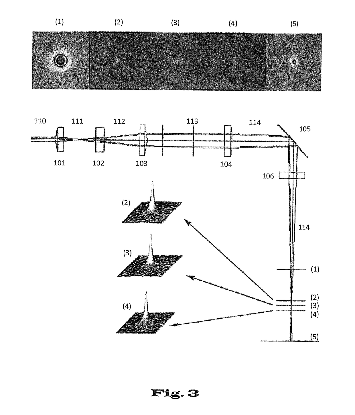
[0030]FIG...
PUM
| Property | Measurement | Unit |
|---|---|---|
| length | aaaaa | aaaaa |
| distance | aaaaa | aaaaa |
| distance | aaaaa | aaaaa |
Abstract
Description
Claims
Application Information