Structure for mounting fuel cell stack

a fuel cell and stack technology, applied in the direction of fuel cells, electrical appliances, electrochemical generators, etc., can solve the problems of lowering the output of the stack, gas diffusion, current-voltage drop,

Active Publication Date: 2018-10-02
HYUNDAI MOTOR CO LTD
View PDF20 Cites 5 Cited by
  • Summary
  • Abstract
  • Description
  • Claims
  • Application Information

AI Technical Summary

Benefits of technology

[0038]The present disclosure has been made in an effort to solve the above-described problems associated with prior art and it is an object of the present disclosure to provide an improved structure for mounting a fuel cell stack that mounts a fuel cell stack in an enclosure or a frame without structural modification even when a stack length (length in a cell stacking direction) is changed without restricting a degree of freedom to change the dimensions in a longitudinal direction of the stack.
[0042]In still another preferred embodiment, the second mounting mechanism may restrict translation of the second mounting part of the fuel cell stack in a direction perpendicular to the longitudinal direction of the stack and rotation of the second mounting part.

Problems solved by technology

When the surface pressure is too low, the contact resistance between the bipolar plate / gas diffusion layer / membrane-electrode assembly is increased, resulting in current-voltage drops.
When the surface pressure is too high, the gas diffusion layers are excessively compressed with the result that gas diffusion is difficult, thereby lowering stack output.
Reduction of the fastening force due to aging of the stack may cause a reduction of surface pressure on the gaskets as well as reduction of the output performance of the stack, resulting in poor airtightness of the reaction gases and the coolant.
In addition, the surface pressure may be reduced due to thermal shrinkage of the gaskets applied to the bipolar plates at a lower temperature of −30 to −20 C. When the surface pressure is excessively reduced, poor airtightness may result.
This results in an increase in ohmic loss, thereby lowering efficiency of the fuel cell.
Consequently, the following problems are caused when mounting the stack in the enclosure or the frame.
As a result, it is not possible to actively respond to the change in length of the stack by repair or by the use of the elastic mechanism.

Method used


Image

  • Structure for mounting fuel cell stack
  • Structure for mounting fuel cell stack
  • Structure for mounting fuel cell stack

Examples


Embodiment Construction

[0062]Hereinafter reference will now be made in detail to various embodiments of the present disclosure, examples of which are illustrated in the accompanying drawings and described below. While the disclosure will be described in conjunction with exemplary embodiments, it will be understood that present description is not intended to limit the disclosure to those exemplary embodiments. On the contrary, the disclosure is intended to cover not only the exemplary embodiments, but also various alternatives, modifications, equivalents and other embodiments, which may be included within the spirit and scope of the disclosure as defined by the appended claims.

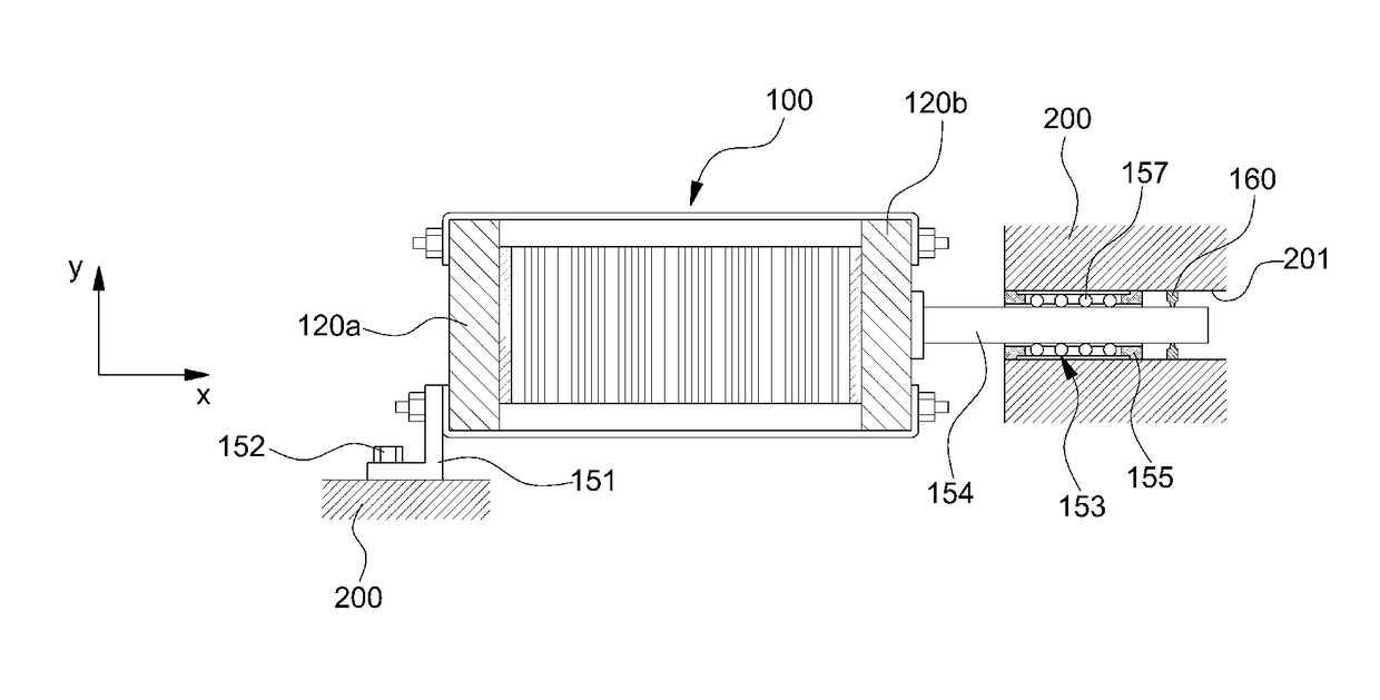
[0063]The present disclosure provides an improved structure for mounting a fuel cell stack that mounts a fuel cell stack in an enclosure or a frame without structural modification even when a stack length (length in a cell stacking direction) is changed without restricting a degree of freedom to change the dimensions in a longitudina...


PUM

PropertyMeasurementUnit
structureaaaaaaaaaa
surface pressureaaaaaaaaaa
lengthaaaaaaaaaa

Abstract

A structure for mounting a fuel cell stack in an enclosure or a frame includes a first mounting mechanism for fastening and mounting a first mounting part located at a first side of the fuel cell stack in a longitudinal direction of the stack, which is a cell stacking direction, to the enclosure or the frame in a completely fixing fashion, and a second mounting mechanism for mounting a second mounting part located at a second side of the fuel cell stack in the longitudinal direction of the stack to the enclosure or the frame in a state of being movable in the longitudinal direction of the stack.

Description

CROSS-REFERENCE TO RELATED APPLICATION[0001]This application claims, under 35 U.S.C. § 119(a), the benefit of priority to Korean Patent Application No. 10-2015-0054602, filed on Apr. 17, 2015 with the Korean Intellectual Property Office, the entire contents of which are incorporated herein by reference.TECHNICAL FIELD[0002]The present disclosure relates to a structure for mounting a fuel cell stack. More particularly, it relates to an improved structure for mounting a fuel cell stack that mounts a fuel cell stack in an enclosure, or a frame, without structural modification when a stack length (length in a cell stacking direction) is changed without restricting a degree of freedom to change the dimensions in a longitudinal direction of the stack.BACKGROUND[0003]A fuel cell is an energy converting device that converts chemical energy of fuel into electric energy through an electrochemical reaction. The fuel cell may be used not only to supply power for industries, homes, and vehicles ...

Claims


Application Information

Patent Timeline
Patent Type & Authority Patents(United States)
IPC IPC(8): H01M8/2404H01M8/248
CPCH01M8/248H01M8/2404Y02E60/50
Inventor SUH, JUNG DO
Owner HYUNDAI MOTOR CO LTD
Why Eureka
Try Eureka