
Inert gas generation system, and an aircraft fuel tank inerting system implementing said inert gas generation system

a technology of inert gas and generation system, which is applied in the direction of transportation and packaging, separation of dispersed particles, and separation of separation processes, etc., can solve the problems of increased aircraft weight, large size of inert gas generation system, and excessive consumption of kerosene, etc., and achieve low oxygen content and high quality

Active Publication Date: 2018-10-23
SAFRAN AEROTECHNICS
View PDF17 Cites 0 Cited by
  • Summary
  • Abstract
  • Description
  • Claims
  • Application Information

AI Technical Summary

Benefits of technology

[0011]One of the objects of the invention is therefore to remedy these drawbacks by proposing an inert gas generation system that allows for an inert gas of high quality, to be generated notably in terms of purity, and low oxygen content.
[0012]Another object of the invention is to provide an inert gas generation system that can be adjusted to the needs and flight phase of the aircraft.
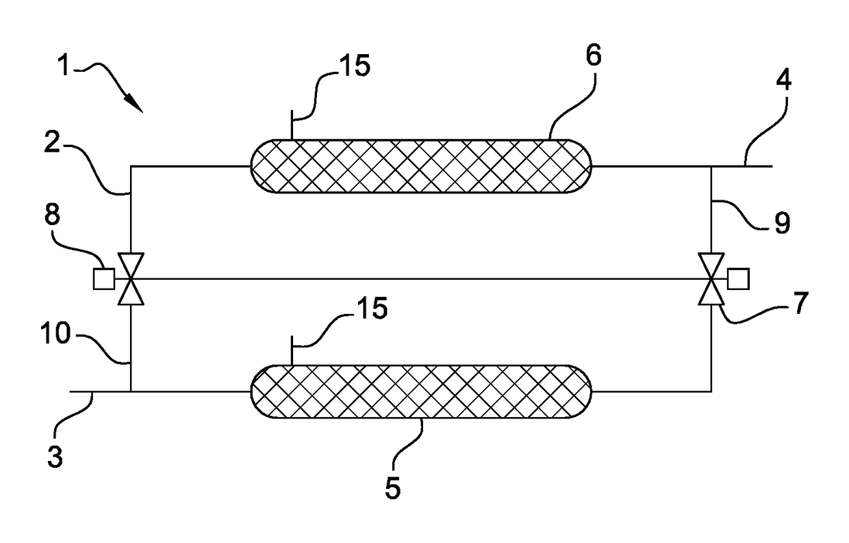
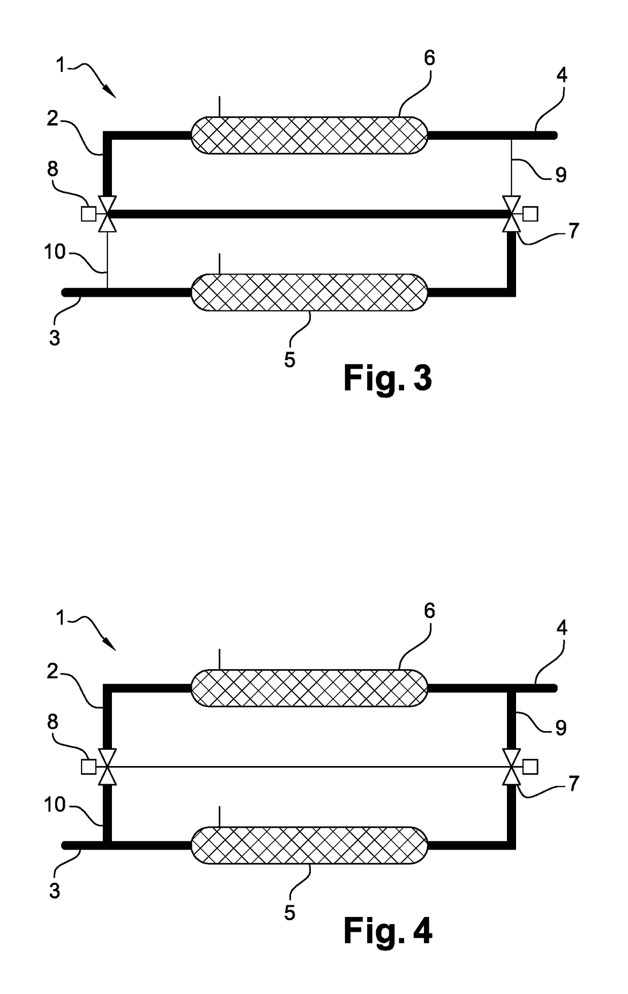
[0014]The air separation modules are arranged in series such that they allow for an inert gas of very high purity to be generated, i.e., with a very low oxygen content, notably of about 3%. In addition, smaller-sized separation modules may be developed in order to achieve performance similar to a system with larger separation modules and arranged in parallel. The integration of the inert gas generation system into the inerting system of an aircraft is therefore facilitated.
[0016]It is therefore possible to change the arrangement of the air separation modules from series to parallel in order to suit the flight phase and actual inert gas quantity and quality requirements.
[0018]Thus, this invention makes it possible to downsize the filtration equipment, such as the ozone converter and the particulate filter, and to use the air separation modules at a relatively constant flow rate which notably has advantages with respect to the thermal control of the system. The air preparation system of the inerting system may also be downsized.
[0024]Thus, when the aircraft tanks require a high inert gas flow rate, particularly during the descent phase of the aircraft, the invention allows the air separation modules to be changed to a series arrangement such that the inert gas is of a higher quality.

Problems solved by technology

The main drawback of inert gas generation systems known in the prior art is their size.
In fact, the arrangement of the air separation modules results in a generation system that is oversized, for example in terms of the number of modules and filtration components, in relation to the actual flight phase need, which in turn causes excessive consumption of kerosene and an increase in the weight of the aircraft.

Method used


Image

  • Inert gas generation system, and an aircraft fuel tank inerting system implementing said inert gas generation system
  • Inert gas generation system, and an aircraft fuel tank inerting system implementing said inert gas generation system
  • Inert gas generation system, and an aircraft fuel tank inerting system implementing said inert gas generation system

Examples


Embodiment Construction

[0031]In reference to FIG. 1, the invention relates to an inert gas generation system (1) comprising an air circuit (2) to deplete oxygen in order to generate a nitrogen-enriched inert gas.

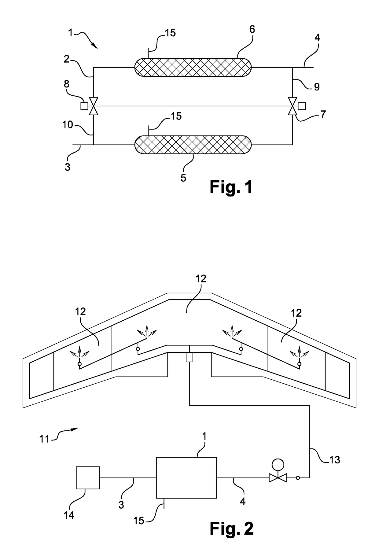
[0032]In reference to FIG. 2, the generation system (1) is notably intended to be used in an inerting system (11) for at least one aircraft fuel tank (12). To this end, the inert gas generation system (1) comprises an air inlet (3) supplied with bleed air diverted from at least one engine and / or air from a passenger cabin and / or air from outside the aircraft via an air preparation system (14) that uses a compressor, and an inert gas outlet (4) connected to distribution means (13) for the inert gas to the fuel tank(s) (12). The generation system (1) also comprises an oxygen-enriched gas outlet (15).

[0033]The inerting system (11) allows an inert gas to be generated and introduced into said aircraft fuel tank(s) (12) for safety reasons in order to reduce the risk of explosion from said tanks. The inj...


PUM


Abstract

An inert gas generation system from a flow of air, notably for an inerting system for at least one aircraft fuel tank. The generation system includes an air circuit having an air inlet, an inert gas outlet, and a first and a second air separation module arranged in series on the air circuit to deplete oxygen within the air and to generate a nitrogen-enriched inert gas.

Description

FIELD OF THE INVENTION[0001]This invention relates to the art of inert gas generation systems, notably used in inerting systems for at least one fuel tank of an aircraft such as an airplane, a helicopter or similar.BACKGROUND OF THE INVENTION[0002]In the art of aeronautics, the use of inerting systems is well known for the generation of an inert gas, such as nitrogen or any other inert gas such as carbon dioxide, and for introducing said inert gas into fuel tanks for safety reasons in order to reduce the risk of explosion from said tanks.[0003]A conventional, prior art inerting system typically includes an on board inert gas generation system (OBIGGS) supplied with air, for example with bleed air diverted from at least one engine. The bleed air diverted from at least one engine is currently the most widely used model. In such a system, the bleed air is typically routed from one or more engines at the opening known as the intermediate pressure port and / or the opening known as the hig...

Claims


Application Information

Patent Timeline
Patent Type & Authority Patents(United States)
IPC IPC(8): B01D53/22B01D71/02B64D37/02B64D37/32
CPCB01D53/226B01D71/028B64D37/02B64D37/32B01D2053/221B64D37/00B01D71/0281
Inventor CLARIS, CHRISTOPHE
Owner SAFRAN AEROTECHNICS
Learn More