
Oil dilution estimation and mitigation control in a fuel injected engine

a technology of oil dilution estimation and mitigation control, which is applied in the direction of electric control, machines/engines, instruments, etc., can solve the problems of easy increase of mixing amount of water into oil accumulated in the oil pan, poor lubrication, and so as to effectively restrain the clogging of the mesh and prevent the occurrence of a malfunction

Inactive Publication Date: 2018-10-23
TOYOTA JIDOSHA KK
View PDF7 Cites 2 Cited by
  • Summary
  • Abstract
  • Description
  • Claims
  • Application Information

AI Technical Summary

Benefits of technology

The patent text describes a method to prevent malfunctions in alcohol-containing fuel engines, such as poor lubrication and clogging of the oil strainer. The method involves estimating the amount of water mixed into the engine oil and increasing the mixing amount of fuel into the oil accordingly. This prevents the water from freezing and causing malfunctions in the engine. Additionally, the method takes into account the alcohol concentration in the fuel, which further enhances the efficiency of fuel mixing into the oil.

Problems solved by technology

Therefore, more condensed water is generated in a crankcase or the like at the time when a temperature of the engine is low like a non-warm-up state, which easily increases a mixing amount of water into the oil accumulated in the oil pan.
The water thus mixed in the oil may be frozen in a cold district or the like, for example, and a generated block of ice might cause clogging in the mesh or the like of the oil strainer.
This disturbs circulation of the oil in a lubrication system of the engine, which causes poor lubrication and also causes such a concern that a malfunction of a hydraulic device that receives supply of the oil may occur.
As a result, the water mixed in the oil does not evaporate but is accumulated, which may increase a possibility that the block of ice thus generated in the oil pan causes a problem, as described above.

Method used


Image

  • Oil dilution estimation and mitigation control in a fuel injected engine
  • Oil dilution estimation and mitigation control in a fuel injected engine
  • Oil dilution estimation and mitigation control in a fuel injected engine

Examples


Embodiment Construction

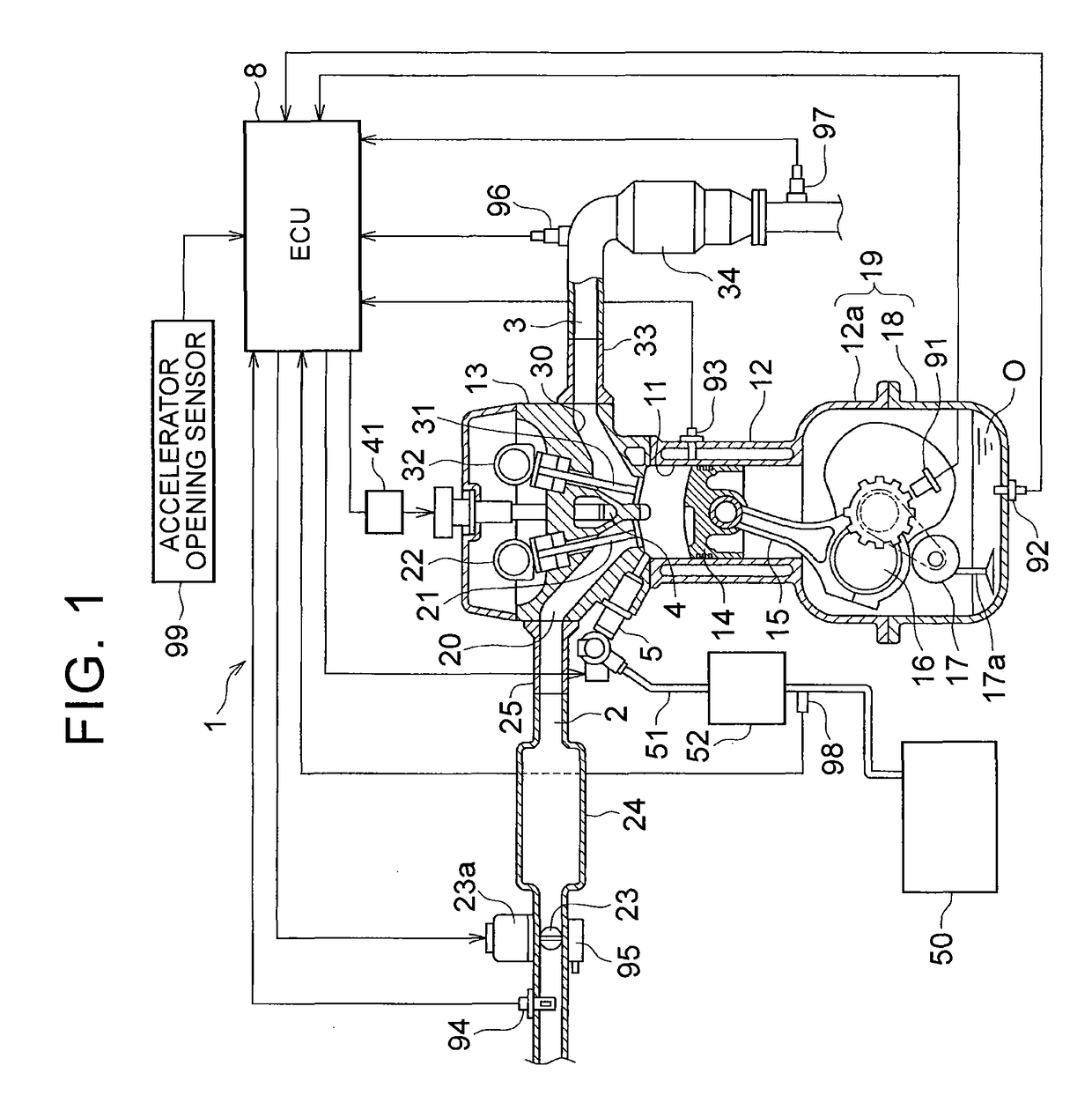
[0030]The following describes an embodiment in which the present invention is applied to a cylinder direct injection engine provided in an FFV. FIG. 1 illustrates only one cylinder 11, but the engine 1 of the present embodiment includes a cylinder block 12 provided with four cylinders 11 arranged in line, for example, and a cylinder head 13 attached to an upper part of the cylinder block 12. A piston 14 is inserted into each of the cylinders 11 in a reciprocating manner, and the piston 14 is connected to a crankshaft 16 via a connecting rod 15.

[0031]That is, an oil pan 18 that accumulates engine oil O (hereinafter just referred to as the oil O) therein is attached to a lower part 12a of the cylinder block 12, and a crankcase 19 that accommodates the crankshaft 16 therein is constituted by the oil pan 18 and the lower part 12a of the cylinder block 12. A crank position sensor 91 is disposed in the crankcase 19, and an oil temperature sensor 92 is disposed in a bottom of the oil pan 1...


PUM


Abstract

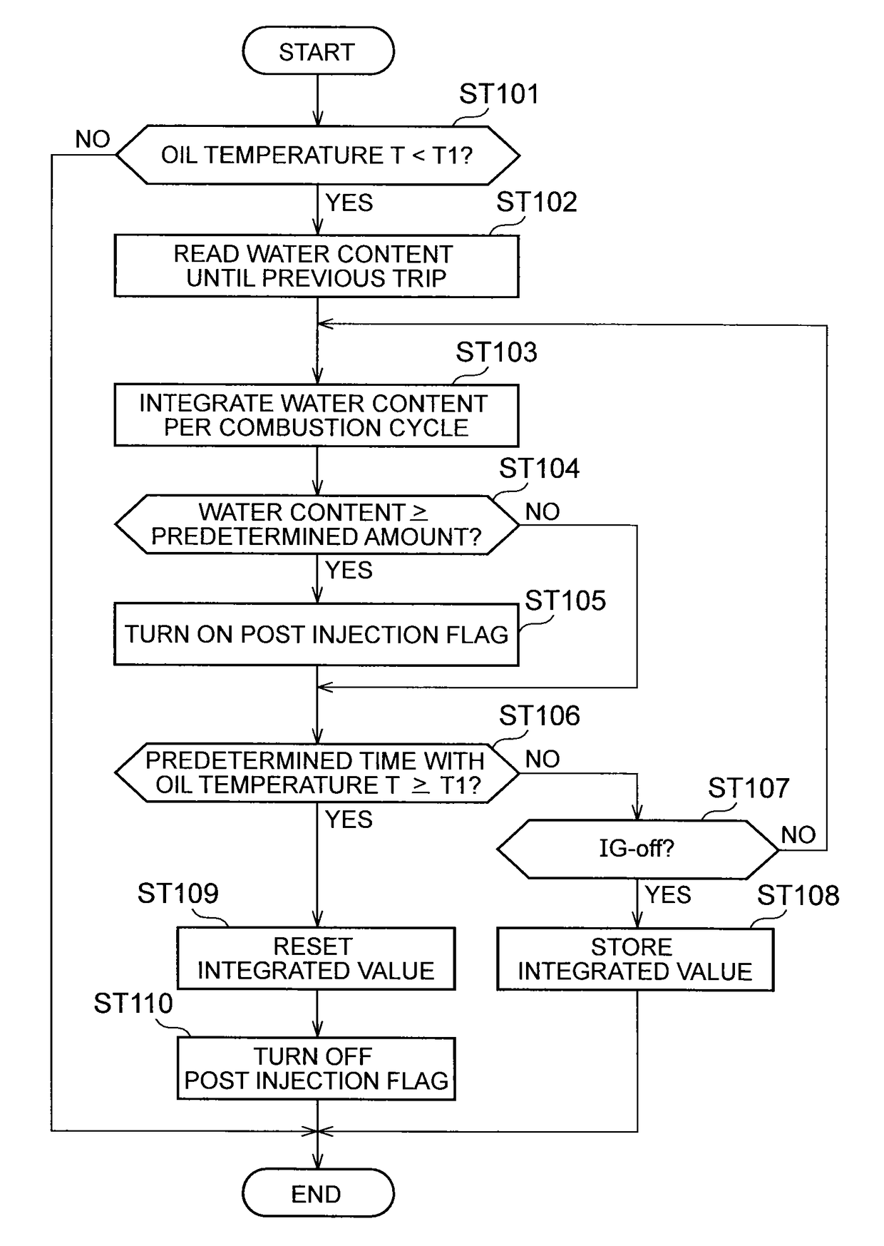
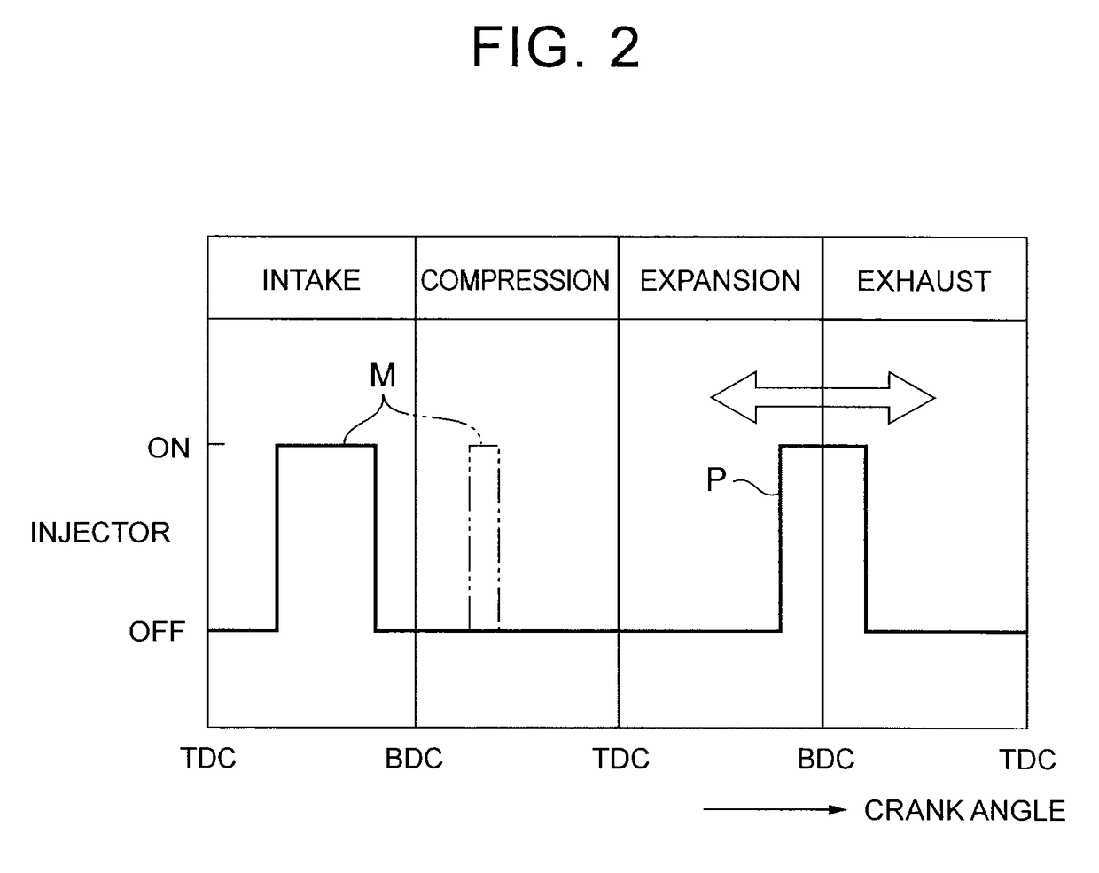
A control device for an engine includes an electronic control unit configured to estimate a water content mixed in engine oil based on a history of a fuel injection amount during an operation of the engine and restrain freezing of water such that, when the water content thus estimated is a predetermined amount or more, the electronic control unit increases a mixing amount of the fuel into the engine oil as compared with a case where the water content thus estimated is less than the predetermined amount. The control device estimates the water content mixed in the engine oil as a function of an integrated value of water content while an oil temperature of the engine is less than a predetermined temperature.

Description

INCORPORATION BY REFERENCE[0001]The disclosure of Japanese Patent Application No. 2015-078681 filed on Apr. 7, 2015 including the specification, drawings and abstract is incorporated herein by reference in its entirety.BACKGROUND[0002]1. Field of the Invention[0003]The present invention relates to a control device for an engine, particularly to a fuel injection control technique in an engine using an alcohol-containing fuel.[0004]2. Description of Related Art[0005]Conventionally, as a fuel for an engine provided in a vehicle, a fuel containing alcohol such as methanol or ethanol may be used as well as gasoline and light oil (see Japanese Patent Application Publication No. 2012-077732 (JP 2012-077732 A), for example). A vehicle provided with such a type of engine is generally called a flexible fuel vehicle (hereinafter referred to as FFV), and by using an alcohol-containing fuel, environmental performance such as improvement of exhaust-gas emission and reduction of consumption of a f...

Claims


Application Information

Patent Timeline
Patent Type & Authority Patents(United States)
IPC IPC(8): G01M15/00F01M5/04F02D19/06F02D41/40F02D19/08F02D41/00F02D41/38
CPCF02D41/0025F01M5/04F02D19/0655F02D19/084F02D19/088F02D41/405Y02T10/44F02D2200/023F02D2200/0612F02D2250/11F16N2200/20Y02T10/36F02D2041/389F02D19/08F02D41/04Y02T10/30Y02T10/40
Inventor KITTAKA, TOMOYUKI
Owner TOYOTA JIDOSHA KK
Learn More