
Dose synthesis card for use with automated biomarker production system

a biomarker and automated technology, applied in the direction of nuclear engineering, chemical/physical/physicochemical processes, therapy, etc., can solve the problems of insufficient traditional 45 to 60 minutes required for quality control tests on radiopharmaceuticals produced in macro-scale, and the removal or significant reduction of transportation phase does not eliminate the need. , to achieve the effect of reducing the number of steps

Active Publication Date: 2018-10-23
BEST ABT INC
View PDF23 Cites 0 Cited by
  • Summary
  • Abstract
  • Description
  • Claims
  • Application Information

AI Technical Summary

Benefits of technology

[0014]The accelerator produces per run a maximum quantity of radioisotope that is approximately equal to the quantity of radioisotope required by the microfluidic chemical production module to synthesize ten doses of biomarker. Chemical synthesis using microreactors or microfluidic chips (or both) is significantly more efficient than chemical synthesis using conventional (macroscale) technology. Percent yields are higher and reaction times are shorter, thereby significantly reducing the quantity of radioisotope required in synthesizing a unit dose of radiopharmaceutical. Accordingly, because the accelerator is for producing per run only such relatively small quantities of radioisotope, the maximum power of the beam generated by the accelerator is approximately two to three orders of magnitude less than that of a conventional particle accelerator. As a direct result of this dramatic reduction in maximum beam power, the accelerator is significantly smaller and lighter than a conventional particle accelerator, has less stringent infrastructure requirements, and requires far less electricity. Additionally, many of the components of the small, low-power accelerator are less expensive than the comparable components of conventional accelerators. Therefore, it is feasible to use the low-power accelerator and accompanying CPM within the grounds of the site of treatment. Because radiopharmaceuticals need not be synthesized at a central location and then transported to distant sites of treatment, less radiopharmaceutical need be produced, and different isotopes, such as carbon-11, may be used if desired.
[0016]The sample card and quality control module allow operators to conduct quality control tests in reduced time using micro-scale test samples from the radiopharmaceutical solution. The sample card works in conjunction with the CPM to collect samples of radiopharmaceutical solution on the scale of up to 100 microliters per sample. The sample card then interacts with the quality control module (or QCM) to feed the samples into a number of test vessels, where the samples undergo a number of automated diagnostic tests. Because the quality control tests are automated and run in parallel on small samples, the quality control testing process may be completed in under 20 minutes. Further, under the traditional system of macroscale radiopharmaceutical synthesis and quality control testing, a radiopharmaceutical solution would be produced as a batch, and quality control tests would be performed on the entire batch, with each batch producing several doses of radiopharmaceutical. Here, because the PET biomarker production system produces approximately one unit dose per run, at least some quality control tests may be performed on every dose, rather than on the batch as a whole.

Problems solved by technology

However, eliminating or significantly reducing the transportation phase does not eliminate the need to perform quality control tests on the CPM and the resultant radiopharmaceutical solution itself.
The traditional 45 to 60 minutes required for quality control tests on radiopharmaceuticals produced in macro scale is clearly inadequate.

Method used


Image

  • Dose synthesis card for use with automated biomarker production system
  • Dose synthesis card for use with automated biomarker production system
  • Dose synthesis card for use with automated biomarker production system

Examples


Embodiment Construction

[0045]A chemical production module and dose synthesis card for a PET biomarker radiopharmaceutical production system are described more fully hereinafter. This invention may, however, be embodied in many different forms and should not be construed as limited to the embodiments set forth herein. Rather, these embodiments are provided to ensure that this disclosure is thorough and complete, and to ensure that it fully conveys the scope of the invention to those skilled in the art.

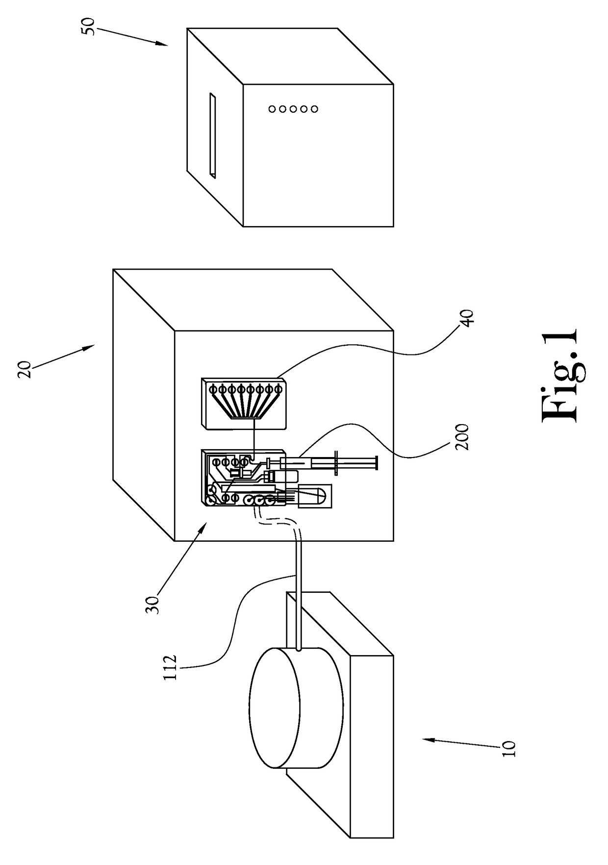
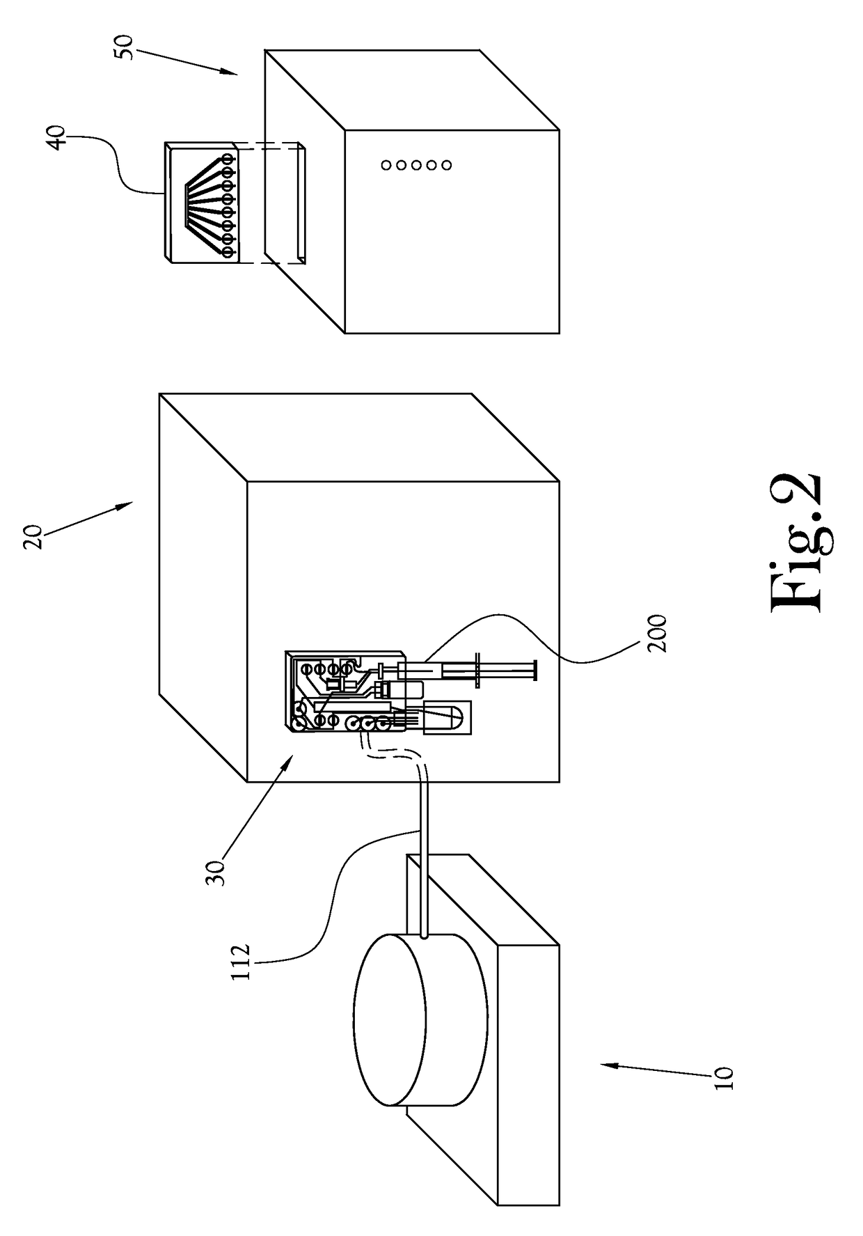
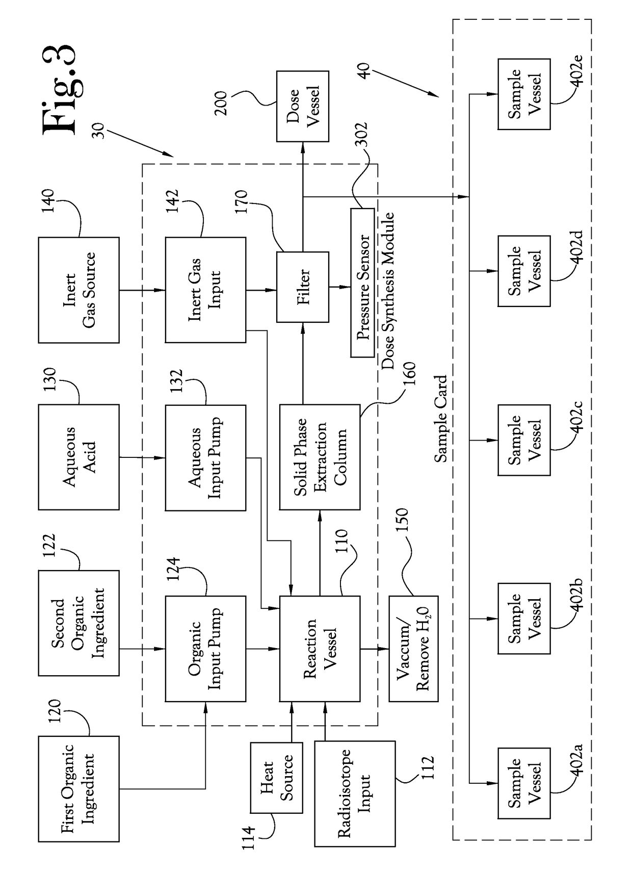
[0046]The chemical production module, the dose synthesis card and the sample card operate in conjunction with a complete PET biomarker production system. As shown in FIG. 1, one embodiment of this PET biomarker production system comprises an accelerator 10, which produces the radioisotopes; a chemical production module (or CPM) 20; a dose synthesis card 30; a sample card 40; and a quality control module (or QCM) 50. Once the accelerator 10 has produced a radioisotope, the radioisotope travels via a radioisoto...


PUM

PropertyMeasurementUnit
diameteraaaaaaaaaa
pressuresaaaaaaaaaa
energyaaaaaaaaaa

Abstract

Microfluidic radiopharmaceutical production system and process for synthesizing per run approximately, but not less than, ten (10) unit doses of radiopharmaceutical biomarker for use in positron emission tomography (PET). A radioisotope from an accelerator or other radioisotope generator is introduced into a reaction vessel, along with organic and aqueous reagents, and the mixture heated to synthesize a solution of a pre-selected radiopharmaceutical. The solution is purified by passing through a combination of solid phase extraction purification components, trap and release components, and a filter. The synthesis process reduces waste and allows for production of biomarker radiopharmaceuticals on site and close to the location where the unit dose will be administered to the patient. On-site, as-needed production of radiopharmaceuticals in small doses reduces the time between synthesis of the radiopharmaceutical and administration of that radiopharmaceutical, minimizing loss of active isotopes through decay and allowing production of lesser amounts of radioisotopes overall.

Description

CROSS-REFERENCE TO RELATED APPLICATIONS[0001]This Application is a continuation-in-part of U.S. patent application Ser. No. 13 / 446,334, filed Apr. 13, 2012, which is a continuation-in-part of U.S. patent application Ser. No. 12 / 565,544, filed Sep. 23, 2009, now U.S. Pat. No. 8,333,952, and a continuation-in-part of U.S. patent application Ser. No. 12 / 565,552, filed Sep. 23, 2009. The contents of the foregoing applications are incorporated herein by reference.STATEMENT REGARDING FEDERALLY-SPONSORED RESEARCH OR DEVELOPMENT[0002]Not ApplicableBACKGROUND OF THE INVENTION[0003]1. Field of Invention[0004]This invention concerns a chemical apparatus and process for synthesizing and purifying radiopharmaceuticals for use in positron emission tomography (PET). Specifically, the present invention relates to a system for analyzing a liquid sample of PET biomarker.[0005]2. Description of the Related Art[0006]A biomarker is used to interrogate a biological system and can be created by “tagging” ...

Claims


Application Information

Patent Timeline
Patent Type & Authority Patents(United States)
IPC IPC(8): A61K51/00G21K5/02A61M36/14B01J19/00A61K51/02A61K51/04
CPCG21K5/02A61K51/025A61K51/0402A61K51/0406A61K51/0446A61K51/0453A61K51/0491B01J19/0093A61K51/0455B01J2219/00909B01J2219/00788B01J2219/00873B01J2219/00891B01J2219/00905
Inventor MCFARLAND, AARONANZELLOTTI, ATILIOHILLESHEIM, DANIELBROWN-PROCTOR, CLIVEKHACHATURIAN, MARK HAIGLAND, ANDREW
Owner BEST ABT INC
Learn More