Thermal non-contact voltage and non-contact current devices

Active Publication Date: 2018-11-06
JOHN FLUKE MFG CO INC
View PDF90 Cites 6 Cited by
  • Summary
  • Abstract
  • Description
  • Claims
  • Application Information

AI Technical Summary

Benefits of technology

[0006]In operation, the at least one processor may estimate an amount of power loss in an insulated conductor of the electrical circuit over a period of time; and at least one of: present the estimated amount of power loss via the display subsystem; or communicate the estimated amount of power loss to an external device over a wired or wireless communications interface. The period of time may include at least one of a number of days, a number of weeks, a number of months, or a number of years. In operation, the at least one processor may estimate the amount of power loss in the insulated conductor relative to an expected amount of power loss in the insulated conductor. In operation, the at least one processor may determine an estimated cost associated with the estimated amount of power loss; and present the estimated cost via the display subsystem. The NVMT may include at least two non-contact voltage sensors which allow for concurrent measurement of two different locations of the electrical circuit. The NCMT may include at least one of a fluxgate sensor, a Hall Effect sensor, a Rogowski coil, a current transformer, or a giant magnetoresistance (GMR) magnetic sensor. The NVMT may include at least one of a capacitive divider type voltage sensor, a reference signal type voltage sensor, or a multi-capacitor type voltage sensor.

Problems solved by technology

In operation, the at least one processor may determine an estimated cost associated with the estimated amount of power loss; and present the estimated cost via the display subsystem.

Method used


Image

  • Thermal non-contact voltage and non-contact current devices
  • Thermal non-contact voltage and non-contact current devices
  • Thermal non-contact voltage and non-contact current devices

Examples


Embodiment Construction

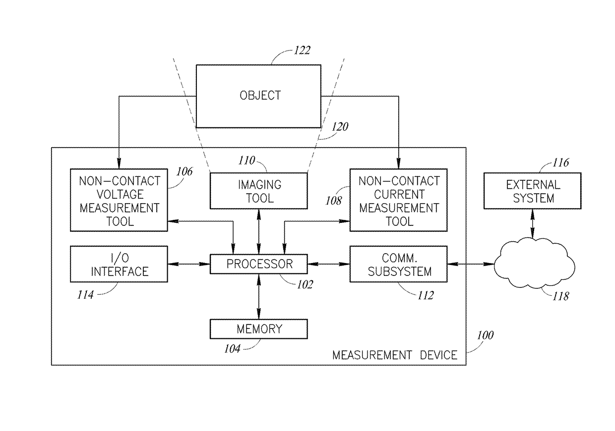
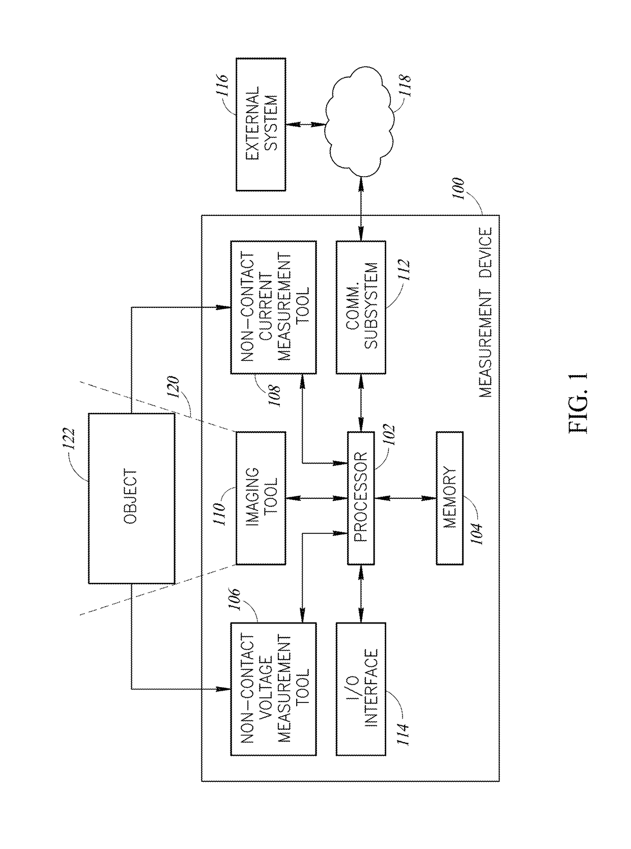
[0022]One or more implementations of the present disclosure provide systems and methods that provide thermal imaging and non-contact voltage or current measurement sensors to detect or measure abnormal conditions in electrical circuits. Such systems and methods may be implemented in a single test device, or in wired combinations, or in wireless communication implementations with multiple test devices and / or accessories, or in combination with one or more additional devices, such as a mobile phone, tablet computer, personal computer (PC), cloud-based server, etc.

[0023]In at least some implementations, a thermal imaging subsystem or tool of a measurement device that includes an infrared sensor may first discover and image one or more thermal anomalies in an object, such as an electrical circuit. Either the user, or the measurement device, may then analyze the detected heat pattern, which may be indicative of either localized high-resistance electrical connections, or high-resistance d...


PUM


Abstract

Systems and methods detect abnormal conditions in electrical circuits by providing thermal imaging combined with non-contact measurements of current and voltage. Such systems may be implemented in a single test device, or in wired combinations, or in wireless communication implementations with multiple test devices and/or accessories, or in combination with one or more additional devices, such as a mobile phone, tablet, personal computer (PC), cloud-based server, etc. A thermal imaging tool that includes an infrared sensor may first discover and image one or more thermal anomalies in an object, such as an electrical circuit. One or more non-contact current or voltage sensors may be used to measure current and/or voltage, which allows for determination of the power loss at the measured location. The power loss may be used to determine an estimation of the abnormal resistive power losses in a circuit, as well as the costs associated therewith.

Description

BACKGROUNDTechnical Field[0001]The present disclosure generally relates to non-contact measurement or detection of various properties of electrical circuits.Description of the Related Art[0002]High-resistance electrical connections can result in a loss of power in an electrical circuit. Such connections are commonly referred to as “resistive power losses,”“copper losses,” or “I2R losses.” This equation is a permutation of Ohm's Law, V=IR, which describes the relationship between electrical current (I), electrical voltage (V) and electrical resistance (R). A related equation is P=VI, which indicates that power (P) is equal to the current multiplied by the voltage. From the above equations, the power loss may be determined by the equation P=I2R. From this equation, it is known that the energy or power loss increases with the square of the current (I) through the conductor and in proportion to the electrical resistance (R) of the conductor.[0003]In the case of resistive power losses in...

Claims


Application Information

Patent Timeline
Patent Type & Authority Patents(United States)
IPC IPC(8): G01R31/302G01R31/308G01R15/24G01R15/18G01R15/20
CPCG01R31/308G01R15/24G01R15/181G01R15/202G01R15/205G01R19/00G01R21/06G01R23/02G01R23/16G01R25/00G01R21/02G01R21/08H02J13/00001H02J13/00002Y04S10/30Y04S10/40Y02E60/00
Inventor SILVA, LUIS R.STUART, MICHAEL D.
Owner JOHN FLUKE MFG CO INC
Why Eureka
Try Eureka