
Fluid sensor cable assembly, system, and method

a technology of fluid sensor and cable assembly, applied in the field of assembly, system and method, can solve the problems of requiring a significant amount of time to heat the well, affecting the quality of fluid sensor cables, and unable to meet the needs of the user,

Active Publication Date: 2018-11-06
BAKER HUGHES OILFIELD OPERATIONS LLC
View PDF22 Cites 8 Cited by
  • Summary
  • Abstract
  • Description
  • Claims
  • Application Information

AI Technical Summary

Benefits of technology

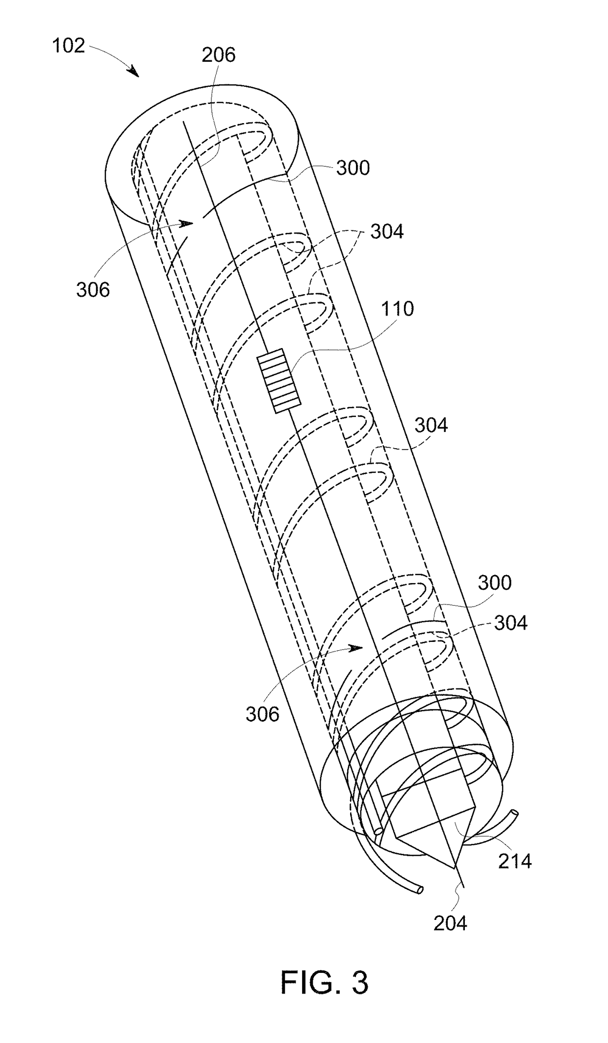
The patent describes a fluid sensor cable assembly that includes a conductive core body and optical fibers with temperature sensors. The assembly is placed in a well to measure the flow of fluid. The conductive core body heats the assembly and the temperature sensors measure the heat output at different locations along the core body. By measuring the phase of the fluid flowing outside the assembly, the system can determine the flow velocity and distribution. The technical effect of this invention is to provide a more accurate and reliable tool for analyzing fluid flow in wells.

Problems solved by technology

These devices can only be placed into non-producing wells, or during time periods that a well is not producing resources (e.g., during times when oil or other resources are not being extracted from the well).
But, it can require a significant amount of time to heat the well, and the well may not heat evenly.
The long heating time and uneven heating can limit the resolution and accuracy of the measurements obtained by the devices.
Additionally, these devices are limited to measuring the flow rates during times when resources are not being extracted from the well.
As a result, these devices cannot provide real time measurements of flow rates, or the rates of flow of fluids in the well during the same time period that one or more of the fluids are being extracted from the well.
For example, the devices may be unable to measure the different amounts of oil, water, and / or gas in the well.
Instead, the devices may be limited to measuring the total rate of flow of these fluids, but not individual flow rates or amounts of the different fluids.

Method used


Image

  • Fluid sensor cable assembly, system, and method
  • Fluid sensor cable assembly, system, and method
  • Fluid sensor cable assembly, system, and method

Examples


Embodiment Construction

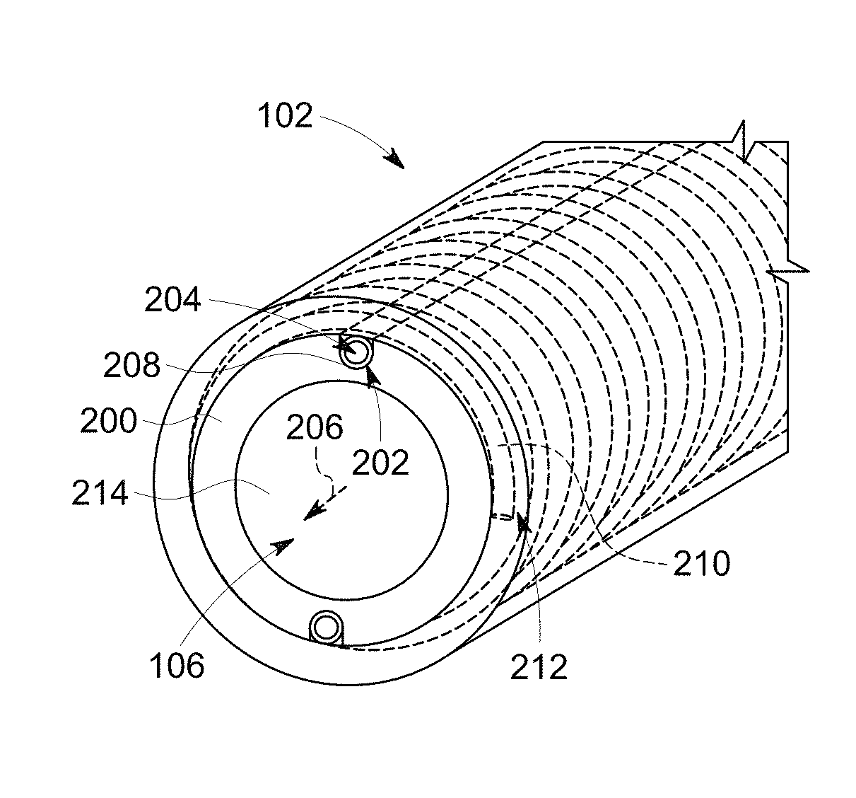
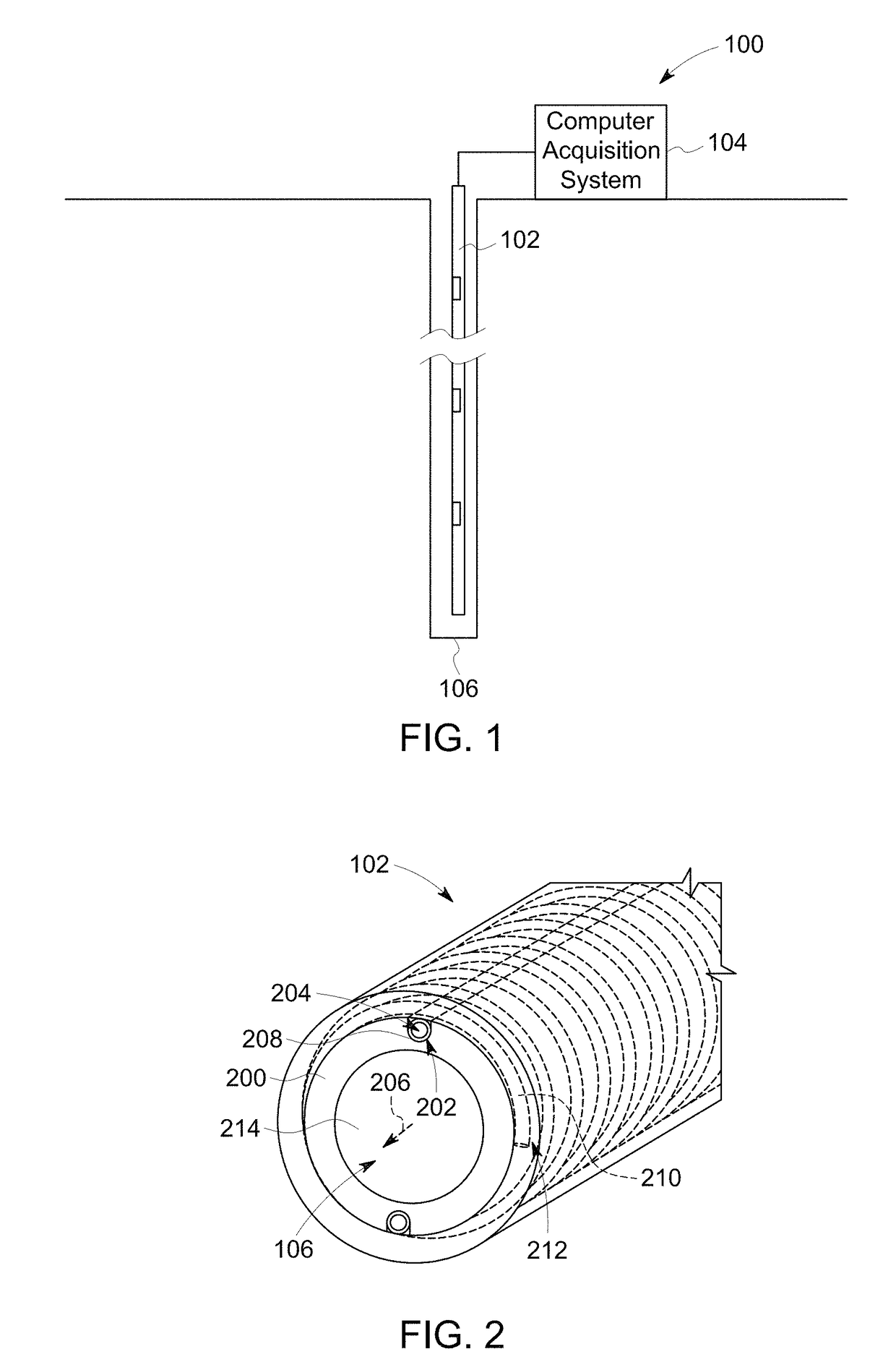
[0026]One or more embodiments of the inventive subject matter described herein provide cable assemblies, measurement systems, and methods that measure distributed phases (e.g., water cut, gas content, etc.) and flow velocity in an oil well. The system and method can provide for real-time logging across multiple perforations, multiple zones and horizontals, as well as enable reservoir production optimization and real time drainage management. The measurements provided by the systems and methods can help validate seismic models of oil fields, improve reservoir planning, increase reserves, improve fracture management, and increase production rates. The systems and methods can log producing formation, as well as net production and be useful in managing the use of water, gas, and sand in wells.

[0027]The systems and methods can use a distributed anemometer with fiber optic distributed temperature sensitive elements coupled to one or more heating element. Radio frequency (RF) signals can b...


PUM

PropertyMeasurementUnit
lengthaaaaaaaaaa
operating temperatureaaaaaaaaaa
lengthaaaaaaaaaa

Abstract

A fluid sensor cable assembly and method uses one or more conductive bodies extending along an elongated core body for conducting a heating current to heat the cable assembly. The one or more conductive bodies also are configured to conduct an interrogation signal and to conduct reflections of the interrogation signal. One or more optical fibers extend along the length of the core body and include temperature sensitive elements at different locations along the length of the core body. The temperature sensitive elements measure heat flux out of the cable assembly at the different locations subsequent to heating the cable assembly and communicate the heat flux to a computer acquisition system.

Description

FIELD[0001]Embodiments of the subject matter disclosed herein relate to assemblies, systems, and methods for measuring fluid velocities and / or measuring fluid phases.BACKGROUND[0002]Multiphase measurement devices can be placed into wells to measure the individual phase flow rates of different phases flowing in the wells. These devices can only be placed into non-producing wells, or during time periods that a well is not producing resources (e.g., during times when oil or other resources are not being extracted from the well). The devices can measure the flow rates of fluids flowing in the wells. These measurements can be used to improve the production of resources (e.g., oil) from the wells, limit wear and tear (e.g., corrosion) on components in the well (by tracking the amount of water and gas in the well), represent performance of the wells, etc.[0003]Some of these devices measure the flow rates by heating the well with elongated cables extending down into the wells and monitoring...

Claims


Application Information

Patent Timeline
Patent Type & Authority Patents(United States)
IPC IPC(8): G01V9/00E21B47/10G01N27/02G01N9/04G01F1/74G01F1/688E21B47/06G01N25/00
CPCG01V9/005E21B47/1005G01F1/74G01N27/02G01N9/04G01N25/00E21B47/06G01F1/6884E21B47/103
Inventor TSAKALAKOS, LOUCASRUBINSZTAJN, SLAWOMIRGUIDA, RENATOBALASUBRAMANIAM, MAHADEVANLEE, BOON KWEERUSH, BRIAN MAGANNAHMAD, FAISAL RAZIMANDAL, SUDEEPSHANKS, DAVID SIRDA
Owner BAKER HUGHES OILFIELD OPERATIONS LLC
Learn More