Vertical photo alignment method with maintaining position of mask unchanged and manufacture method of liquid crystal display panel utilizing the same

a manufacturing method and technology of liquid crystal display panel, applied in the field of display technology, can solve the problems of affecting the quality of the display panel, affecting the alignment precision loss, damage to the liquid crystal element, etc., and achieve the effect of simple method, high alignment precision and effective reduction of precision loss

Active Publication Date: 2018-11-06
TCL CHINA STAR OPTOELECTRONICS TECH CO LTD
View PDF8 Cites 0 Cited by
  • Summary
  • Abstract
  • Description
  • Claims
  • Application Information

AI Technical Summary

Benefits of technology

[0006]An objective of the present invention is to provide a vertical photo alignment method, in which each pixel region is divided into four sub regions to obtain the alignment film having four alignment directions, and the four sub regions have different alignment directions, and the alignment precision is high, and the method is simple, and the cost is low.
[0007]Another objective of the present invention is to provide a manufacture method of a liquid crystal display panel, which utilizes the aforesaid vertical photo alignment method to respectively implement vertical photo alignment to the CF substrate and the TFT substrate, and the alignment precision is high, and the obtained the liquid crystal display panel possesses the properties of wide view angle, high transmission rate, non color deviation, high contrast and high resolution.
[0034]The benefits of the present invention are: the present invention provides a vertical photo alignment method, and the pixel region is designed to be a square, and the pixel region is divided into four sub regions of equal sizes, and the pattern units on the mask corresponding to the pixel regions comprises the photic region and the shading region, wherein the shape and the size of the photic region are the same as the shape and the size of one sub region of the pixel region. First, the mask is employed to implement UV light irradiation to one sub region of the pixel region according to the certain irradiation angle to obtain the alignment direction of the sub region, and then, the position of the mask and the irradiation direction of the linear UV light are maintained to be unchanged. By rotating the substrate, and the mask continuously employed to implement linear UV light irradiation to the other three sub regions of the pixel region in order according to the certain irradiation angle for sequentially obtaining the alignment directions of the three sub regions. Namely, the alignment directions of the four sub regions of the pixel region are different from one another. Because the mask is constantly steady in the alignment process, the precision loss can be effectively reduced to raise the exposure precision, and thus the alignment precision is high, and the method is simple, and the cost is low; the present invention provides a manufacture method of a liquid crystal display panel, which utilizes the aforesaid vertical photo alignment method to respectively implement vertical photo alignment to the CF substrate and the TFT substrate, and the alignment precision is high, and the alignment directions of the corresponding sub regions on the CF substrate and the TFT substrate are mutually perpendicular, therefore, the obtained the liquid crystal display panel possesses the properties of wide view angle, high transmission rate, non color deviation, high contrast and high resolution.

Problems solved by technology

However, in the rubbing process, the pollutions of the electrostatic and particles will generate due to the contacting friction of the fabric, and these pollutions often cause the damage of the liquid crystal element.
As utilizing the mask for partitioning the panel, the movement of the mask will result in the alignment precision loss and influence the panel quality.

Method used


Image

  • Vertical photo alignment method with maintaining position of mask unchanged and manufacture method of liquid crystal display panel utilizing the same
  • Vertical photo alignment method with maintaining position of mask unchanged and manufacture method of liquid crystal display panel utilizing the same
  • Vertical photo alignment method with maintaining position of mask unchanged and manufacture method of liquid crystal display panel utilizing the same

Examples


Embodiment Construction

[0043]For better explaining the technical solution and the effect of the present invention, the present invention will be further described in detail with the accompanying drawings and the specific embodiments.

[0044]Please refer to FIG. 1. The present invention provides a vertical photo alignment method, comprising steps of:

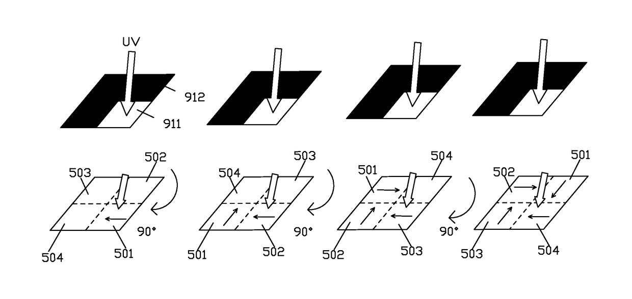
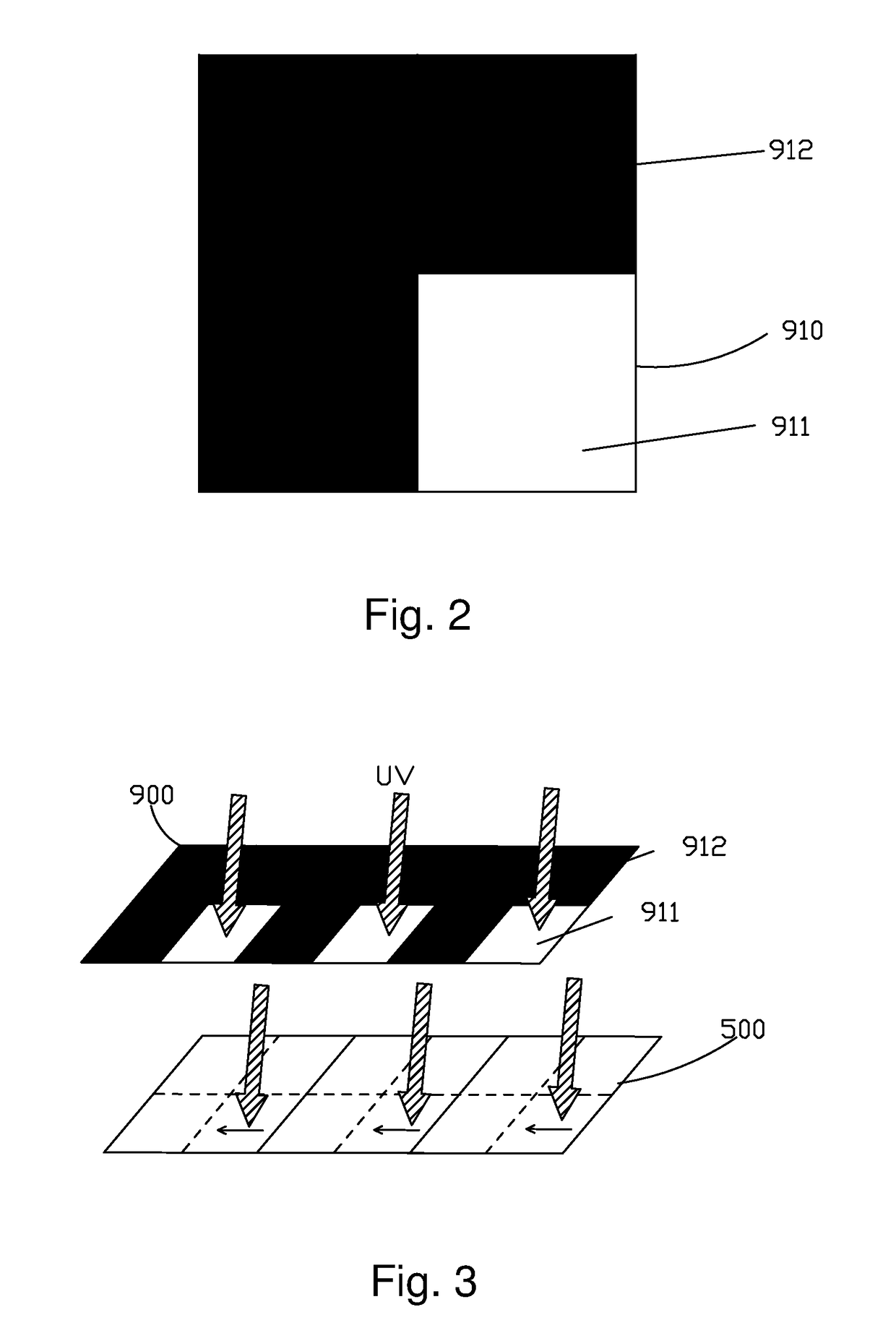
[0045]step 1, providing a substrate, and the substrate comprises a plurality of pixel regions 500 aligned in array, and each pixel region 500 is a square, and the pixel region 500 is divided into four square sub regions of equal sizes;

[0046]Specifically, in the step 1, the provided substrate is a TFT substrate or a CF substrate.

[0047]step 2, coating a layer of photo alignment polymer on the substrate to form a photo alignment film;

[0048]Specifically, in the step 2, the photo alignment polymer coated on the substrate is polyimide material.

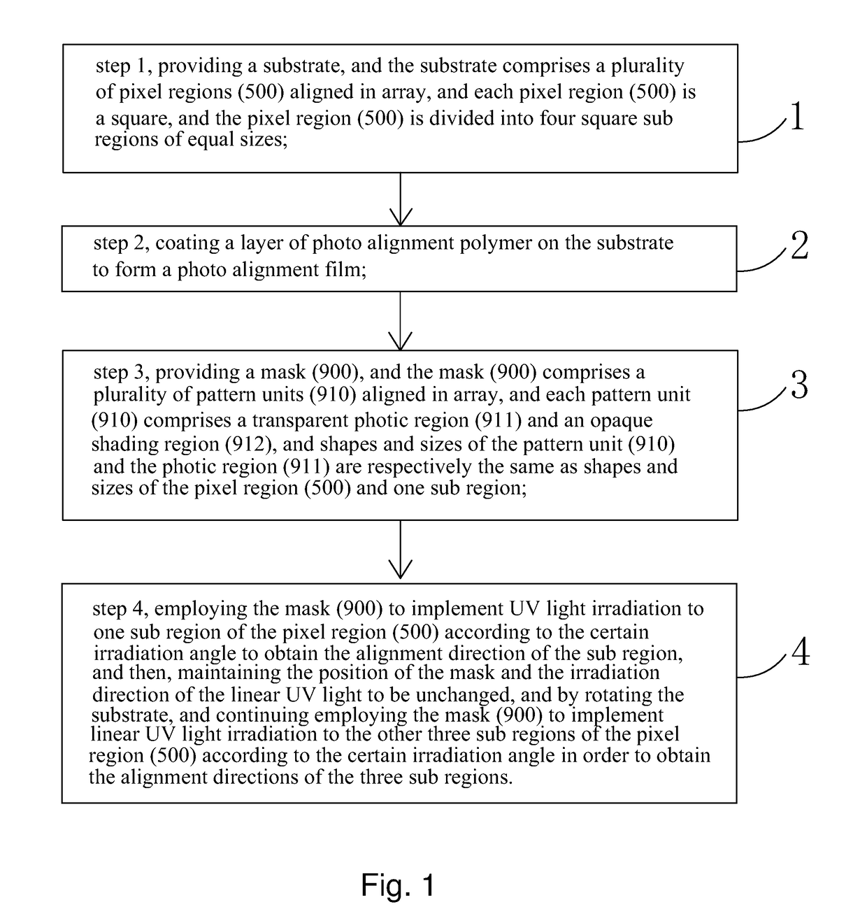
[0049]step 3, providing a mask 900, and the mask 900 comprises a plurality of pattern units 910 aligned in array, and a shape a...


PUM

PropertyMeasurementUnit
sizesaaaaaaaaaa
sizeaaaaaaaaaa
transparentaaaaaaaaaa

Abstract

In a provided vertical alignment method, a pixel region, and the pixel region is divided into four sub regions of equal sizes which each is designed to be a square, and a pattern unit on the mask comprises a photic region corresponding to one sub region and a shading region corresponding to the other three sub regions in shape and size. The mask is employed to implement linear UV light irradiation to one sub region according to a certain irradiation angle to obtain a alignment direction of the one sub region, and then, the position of the mask and the certain irradiation angle of the irradiation are maintained to be unchanged. By rotating the pixel region 90° with three times, and the irradiation is implemented to the other three sub regions. Accordingly, the four sub regions have four alignment directions different from one another.

Description

FIELD OF THE INVENTION[0001]The present invention relates to a display technology field, and more particularly to a vertical photo alignment method and a manufacture method of a liquid crystal display panel.BACKGROUND OF THE INVENTION[0002]The Liquid Crystal Display (LCD) is one of the most widely utilized flat panel displays, and the liquid crystal display panel is the core component of the Liquid Crystal Display. The liquid crystal panel generally comprises a Color Filter Substrate (CF Substrate), a Thin Film Transistor Array Substrate (TFT Array Substrate) and a Liquid Crystal Layer arranged between the two substrates. Generally, the pixel electrode and the common electrode are respectively arranged on the array substrate and the color filter substrate. As the voltages are applied to the pixel electrodes and the common electrodes, the electrical field can be generated in the liquid crystal layer, and the electrical field determines the orientation of the liquid crystal molecules,...

Claims


Application Information

Patent Timeline
Patent Type & Authority Patents(United States)
IPC IPC(8): G02F1/1337G02F1/1335G02F1/1343G02F1/1362G02F1/1333
CPCG02F1/133753G02F1/13439G02F1/13624G02F1/133711G02F1/133788G02F1/133514G02F2001/133742G02F2001/133354G02F1/1333G02F1/133742G02F1/133354
Inventor MA, CHAOMA, XIAOLONGLEE, YUNGJUI
Owner TCL CHINA STAR OPTOELECTRONICS TECH CO LTD
Why Eureka
Try Eureka