Edge banding machine

Active Publication Date: 2018-11-13
OAV EQUIP & TOOLS
View PDF6 Cites 7 Cited by
  • Summary
  • Abstract
  • Description
  • Claims
  • Application Information

AI Technical Summary

Benefits of technology

[0005]The present invention has been accomplished under the circumstances in view. It is one object of the present invention to provide an edge banding machine, which avoids the proble

Problems solved by technology

When the workpiece driven roller 95 wears, the radius of the workpiece driven roller 95 is relatively reduced, at this time, the predetermined length thus measured is inaccurate, resulting in a speed difference between the motor of the glue applicator 94 and the motor of the edge band transmission mechanism 93 an

Method used


Image

  • Edge banding machine
  • Edge banding machine
  • Edge banding machine

Examples


Embodiment Construction

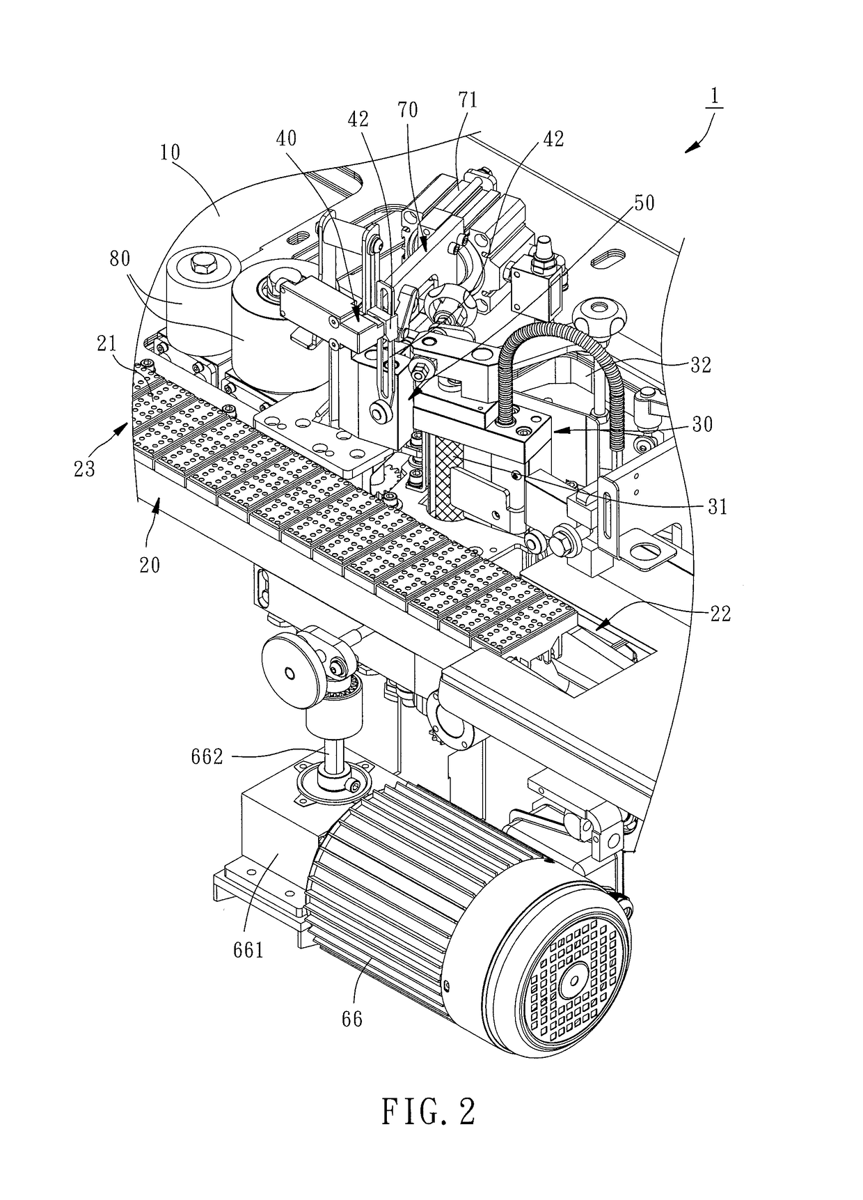
[0022]In order to provide a detailed description of the technical features of the present invention, the following preferred embodiment is given by way of example with reference to the accompanying drawings, in which the feeding mechanism 20 is provided on the front side of the platform 10 as a direction reference.

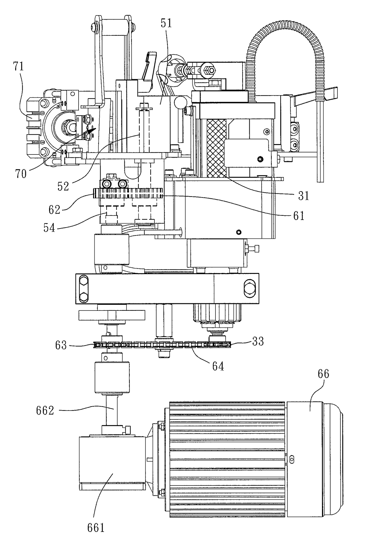
[0023]Referring to FIG. 2, the edge banding machine, referenced by 1, generally comprises a platform 10, a feeding mechanism 20, a glue applicator 30, a sensor 40, an edge band transmission mechanism 50, a cutting tool 70 and a control unit 85. The feeding mechanism 20 is disposed at one side of the platform 10, comprising a conveyor belt 21 driven by a motor (not shown) to deliver a workpiece S to be processed from a feed end 22 to a discharge end 23. Further, a positioning roller (not shown) is disposed above the conveyor belt 21 with a distance defined therebetween. This distance is equal to the height of the workpiece S so that the workpiece S to be processed can be st...


PUM


Abstract

An edge banding machine having a platform, a glue applicator and, an edge band transmission mechanism for affixing an edge band to a workpiece is disclosed. The glue applicator is mounted at the platform, including a glue-applying shaft. The edge band transmission mechanism is mounted at the platform adjacent to the glue applicator, including an edge band transferring shaft disposed in parallel to the glue-applying shaft and a motor connected with the edge band transferring shaft for driving the edge band transferring shaft to rotate. The edge band transferring shaft is connected with the glue-applying shaft so that the edge band transferring shaft and the glue-applying shaft can be synchronously rotated.

Description

BACKGROUND OF THE INVENTION1. Field of the Invention[0001]The present invention relates to edge banding machine, and more particularly to an improved structure of edge banding machine, which can effectively reduce problem of machining error during processing.2. Description of the Related Art[0002]FIG. 1 illustrates a conventional edge banding machine. The edge banding machine 90 comprises a platform 91, a feeding mechanism 92, an edge band transmission mechanism 93 and a glue applicator 94. The feeding mechanism 92 comprises a feeding roller set 921 for feeding a workpiece to be processed forward, enabling the workpiece to be delivered to the edge band transmission mechanism 93 and the glue applicator 94 at the platform 91. When the workpiece is moved to the glue applicator 94, one side of the workpiece is disposed with a layer of hot melt glue for the bonding of an edge band of a predetermined length. The predetermined length of the edge band is determined according to the side len...

Claims


Application Information

Patent Timeline
IPC IPC(8): B29C65/52B29C65/78B29C65/00
CPCB29C65/524B29C65/78B29C66/80B29C63/0026
Inventor JAN, LONG-CHANG
Owner OAV EQUIP & TOOLS
Why Eureka
Try Eureka