Integrated circuit calibration architecture
a technology of integrated circuits and calibration architectures, applied in the field of electronic circuits, can solve the problems of difficult to obtain accurate calibration measurements of such performance in the assembled final system, experience constructive interference, and other signals at other angles experience destructive interference, and achieve the effect of simple testing environment and accurate calibration
- Summary
- Abstract
- Description
- Claims
- Application Information
AI Technical Summary
Benefits of technology
Problems solved by technology
Method used
Image
Examples
first embodiment
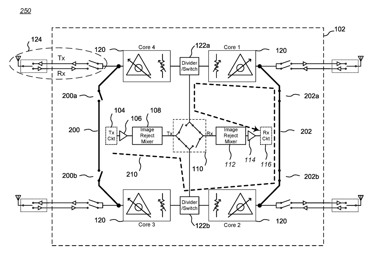
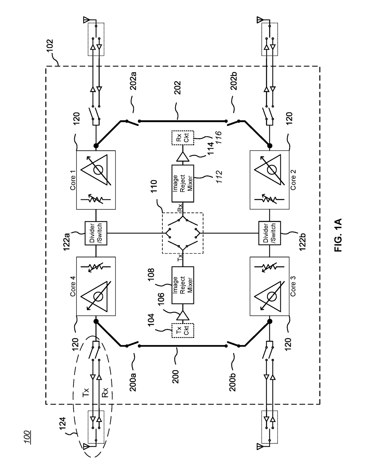
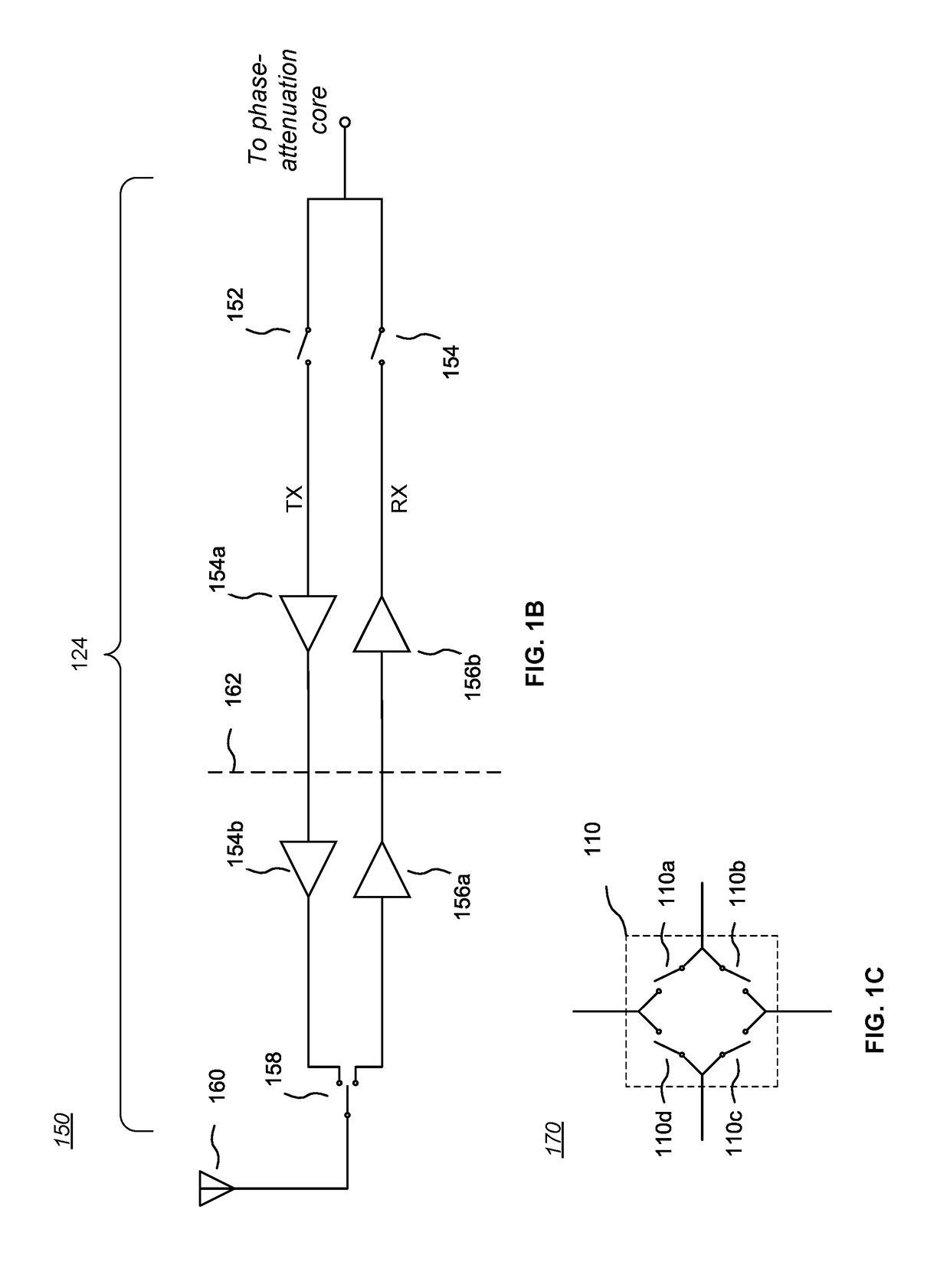
[0021]FIG. 1A is a block diagram 100 of an RF IC 102 (or “chip”) with integrated calibration circuitry suitable for use in a transceiver RF system. This particular example of an RF IC 102 is configured to be coupled to transmit circuitry 104 (labeled “Tx Ckt”) through an isolation and / or drive buffer 106 to a conventional image reject mixer 108, which in turn is coupled to a multi-way switch complex 110 (see also FIG. 1C). Also coupled to the multi-way switch complex 110 through a conventional image reject mixer 112 and an isolation and / or drive buffer 114 is receive circuitry 116 (labeled “Rx Ckt”). The transmit circuitry 104 and the receive circuitry 116 generally will operate at baseband frequencies, but some embodiments may operate at intermediate (IF) or RF frequencies (with appropriate adjustments in other circuitry, such as the image reject mixers 108, 112, if needed; more specifically, if the transmit circuitry 104 and the receive circuitry 116 operate at RF frequencies, the...
second embodiment
[0045]The concepts described above can be extended to include more circuitry that may affect an RF signal conveyed to or from the antennas 160. Thus, while the embodiment of FIG. 1A and FIG. 2 allows for characterization of the phase-attenuation cores 120, it is possible to extend testing to more peripheral circuitry in the RF IC 102, such as the on-chip amplifiers 154a, 156b (see FIG. 1B) in each associated input / output circuit 124. For example, FIG. 3 is a block diagram of an RF IC with integrated calibration circuitry suitable for use in a transceiver RF system. Formed on-chip with the circuit of FIG. 1A are sets of internal switchable periphery cross-circuit calibration (“PC3”) paths 302, 304, each connected to the transmit path TX and the receive path RX of pairs of phase-attenuation cores 120 by associated switches 302a-302d, 304a-304d. (Note that the PC3 paths are essentially the same as C3 paths, differing only in the connection points and number of switches, and are re-name...
third embodiment
[0063]The concepts described above can be extended to include less circuitry that may affect an RF signal conveyed to or from the antennas 160. For example, FIG. 5 is a block diagram of an RF IC with integrated calibration circuitry suitable for use in a transceiver RF system. Formed on-chip with the circuit of FIG. 1A are sets of internal switchable bypass circuit calibration (“BC2”) paths 502, 504, each connected to the reception path Rx by associated switches 502a-502b, 504a-504b. (Note that the BC2 paths are essentially the same as C3 or PC3 paths, differing only in the connection points and number of switches, and are re-named only for clarity in the following description.)
[0064]As illustrated, BC2 path 502 connects to Core 2 through switch 502a, and to Core 3 through switch 502b. Similarly, BC2 path 504 connects to Core 1 through switch 504a, and to Core 4 through switch 504b. The associated BC2 path switches may be implemented, for example, as one or more FETs or MEMS devices...
PUM
 Abstract
Description
Claims
Application Information
 - R&D
- Intellectual Property
- Life Sciences
- Materials
- Tech Scout
- Unparalleled Data Quality
- Higher Quality Content
- 60% Fewer Hallucinations
Browse by: Latest US Patents, China's latest patents, Technical Efficacy Thesaurus, Application Domain, Technology Topic, Popular Technical Reports.
© 2025 PatSnap. All rights reserved.Legal|Privacy policy|Modern Slavery Act Transparency Statement|Sitemap|About US| Contact US: help@patsnap.com


