Method and system for determining cells traversed by a measuring or visualization axis

a technology of determining cells and axis, applied in the field of methods and systems for determining cells situated on axis, can solve the problems of scheme not explaining how to solve the problem of mapping 2d or 3d, computational need explodes, and cannot solve the problem of 2d or 3d mapping problem, etc., to achieve less constraining of computational architecture and ensure precision

Active Publication Date: 2018-11-20
COMMISSARIAT A LENERGIE ATOMIQUE ET AUX ENERGIES ALTERNATIVES
View PDF4 Cites 2 Cited by
  • Summary
  • Abstract
  • Description
  • Claims
  • Application Information

AI Technical Summary

Benefits of technology

[0025]For this purpose, the invention is aimed at providing a scheme for determining the cells requiring fewer resources than the schemes proposed in the prior art. The invention also makes it possible to optimize the phase of mapping the information regarding occupancy in a grid, whatever its dimension, 1D, 2D, 3D, etc., so as to render it much less constraining for the computational architecture and faster, while ensuring precision with respect to traditional floating-point approaches.
[0031]Computation of the value of an, integer, error parameter E by using an error function Errd(M) making it possible to evaluate, in the discretized space, an offset between a point of the space and a straight line connecting the points S and F, said error parameter E being initialized to the value taken by said error function for said initial vertex V0 of the cell cs,

Problems solved by technology

One of the difficulties is to determine, precisely and in a reasonable computation time, the cells liable to be traversed or observed by a moving device so as to associate with them an item of information relating to the presence or to the absence of an obstacle.
One of the problems in the computation of 2D or 3D occupancy grids, when using several heterogeneous sensors positioned at various sites of the space studied, is that the computational need explodes.
Moreover, and independently of any digital representation, the mapping problem is intrinsically tricky since it implements computation utilizing information at various spatial resolutions.
On the other hand, the scheme does not describe how to solve the problem of the mapping of the 2D or 3D information in integer arithmetic.

Method used


Image

  • Method and system for determining cells traversed by a measuring or visualization axis
  • Method and system for determining cells traversed by a measuring or visualization axis
  • Method and system for determining cells traversed by a measuring or visualization axis

Examples


Embodiment Construction

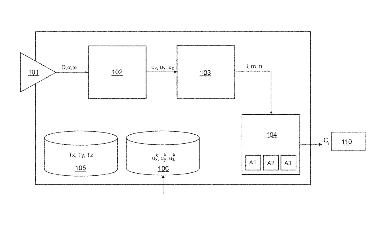
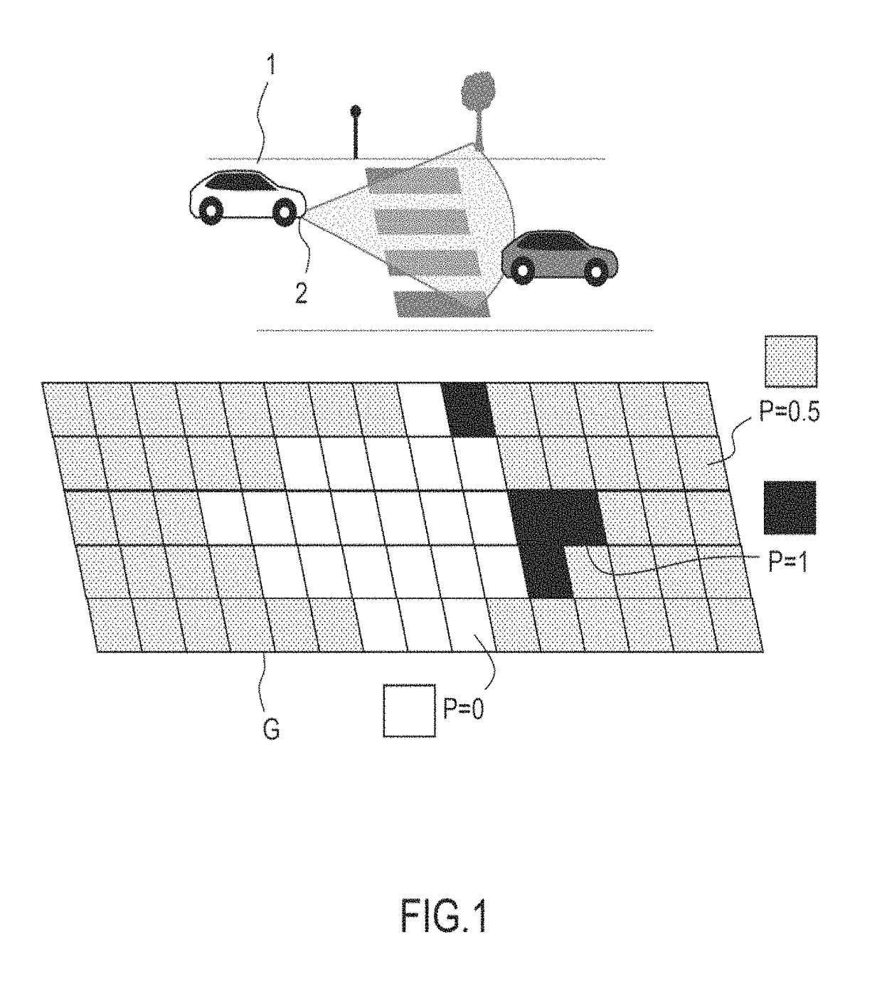
[0083]In order to better elucidate the subject of the invention, the example which follows is given by way of wholly nonlimiting illustration for the detection of obstacles in the case of a car equipped with a camera making it possible to detect obstacles that may be present on its path.

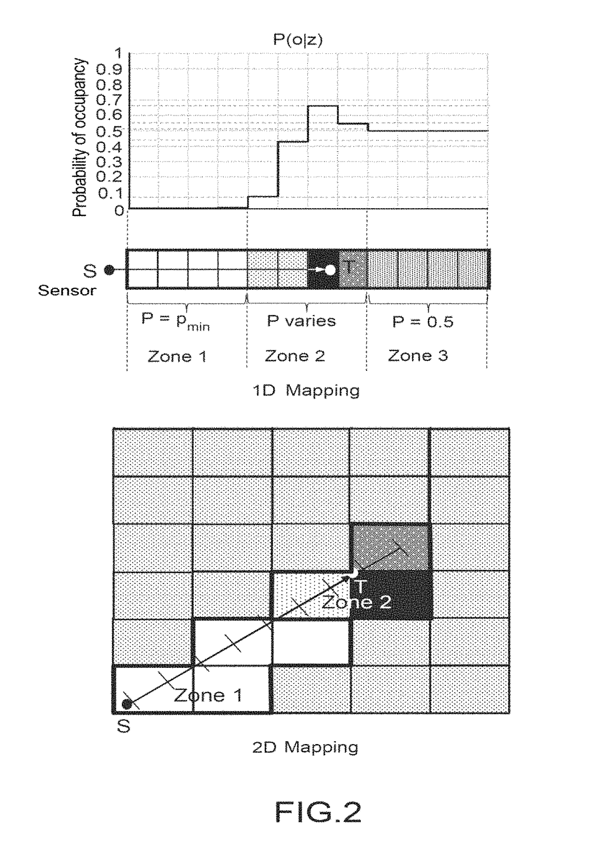
[0084]The occupancy grids are a discretization of the observed space into cells. The mapping of “mono-target” sensor information makes it necessary to be able rapidly to find the cells traversed by a straight line.

[0085]Let S(xS,yS) be the position of the sensor situated on the car, and F(xF,yF) the target detected by the sensor. The cells traversed by the segment [SF] must undergo an occupancy update. The point M(x,y) is on the line containing the segment [SF] if and only if:

Err(M)=(y−ys)·(xF−xS)−(x−xs)·(yF−ys)=0

[0086]It may then be noted that if two points A and B are situated on either side of the line, then we obtain Err(A) and Err(B) with opposite signs. This property makes it possible to deduce...


PUM


Abstract

A method to locate material bodies on an at least 2-dimensional occupancy grid G, having a first resolution stepsize RG, that includes a set of cells represented by vertices and segments connecting these vertices. The method uses a sensor for detecting an obstacle which is positioned at source point S, and includes at least the following steps: acquisition by the sensor of a measurement of the position of a material body detected at a point F; defining the coordinates of a point M by using a space discretized with the aid of a spatial stepsize δ which is finer than the resolution stepsize RG, initializing an integer, error parameter, and calculating the value of the error parameter for at least one first vertex of the cell of the current grid.

Description

CROSS-REFERENCE TO RELATED APPLICATION[0001]This application claims priority to foreign French patent application No. FR 1655104, filed on Jun. 3, 2016, the disclosure of which is incorporated by reference in its entirety.FIELD OF THE INVENTION[0002]The invention relates to a method and a system for determining cells situated on an axis or a path between a first source point and a second point.[0003]The invention applies in electronic perception systems for aiding navigation. Devices of this type are used in the automotive, robotics, drone sectors and in automated production lines, etc., with the aim in particular of detecting and determining the position of a material body liable to be situated on the trajectory of a moving device.BACKGROUND[0004]By “material body” is meant any material substance or object exhibiting an individuality and able to be detected and identified by an appropriate sensor. Thus, inanimate objects, be they natural or artificial, plants, animals, human beings...

Claims


Application Information

Patent Timeline
Patent Type & Authority Patents(United States)
IPC IPC(8): G06T7/70G06K9/00G05D1/00G06F17/10G01S13/93G01S15/93G01S17/93G01S13/931G01S15/931G01S17/931
CPCG06T7/70G05D1/00G06F17/10G06K9/00805G01S17/936G01S13/931G01S15/931G01S17/931G06V20/58
Inventor MOTTIN, JULIENRAKOTOVAO ANDRIAMAHEFA, TIANAPUSCHINI PASCUAL, DIEGODEBICKI, OLIVIER
Owner COMMISSARIAT A LENERGIE ATOMIQUE ET AUX ENERGIES ALTERNATIVES
Why Eureka
Try Eureka