
Two-stage corrosion under insulation detection methodology and modular vehicle with dual locomotion sensory systems

a detection method and technology of corrosion, applied in the direction of instruments, transportation and packaging, optical radiation measurement, etc., can solve the problems of difficult detection of cui, inability to detect cui in the early stages, and the equipment exposed to mist and cooling water towers can be especially vulnerable to cui developmen

Active Publication Date: 2018-11-27
SAUDI ARABIAN OIL CO
View PDF15 Cites 1 Cited by
  • Summary
  • Abstract
  • Description
  • Claims
  • Application Information

AI Technical Summary

Problems solved by technology

Insulated equipment that is exposed to mist and cooling water towers, as well as equipment that is exposed to steam vents can be especially vulnerable to the development of CUI.
CUI is difficult to detect in its early stages as its precursor is merely the accumulation of moisture and water patches underneath the insulation layers, which is not visible from outside of the equipment.
CUI that remains undetected can cause major damage to the equipment and, in severe cases, can even result in the closure of a process unit that features the damaged equipment.
These current practices, however, are time consuming and costly.
Specifically, downtime of the insulated equipment during inspection, replacement of cladding after inspection, and repairs to damaged equipment (e.g., removing damaged insulation) all result in increased costs.
Early detection of CUI can limit the damage to the equipment and thus limit the economic effects of the damage; however, early detection of CUI is difficult due to the time-consuming nature of the current inspection processes and the hidden nature of the precursors of CUI.

Method used


Image

  • Two-stage corrosion under insulation detection methodology and modular vehicle with dual locomotion sensory systems
  • Two-stage corrosion under insulation detection methodology and modular vehicle with dual locomotion sensory systems
  • Two-stage corrosion under insulation detection methodology and modular vehicle with dual locomotion sensory systems

Examples


Embodiment Construction

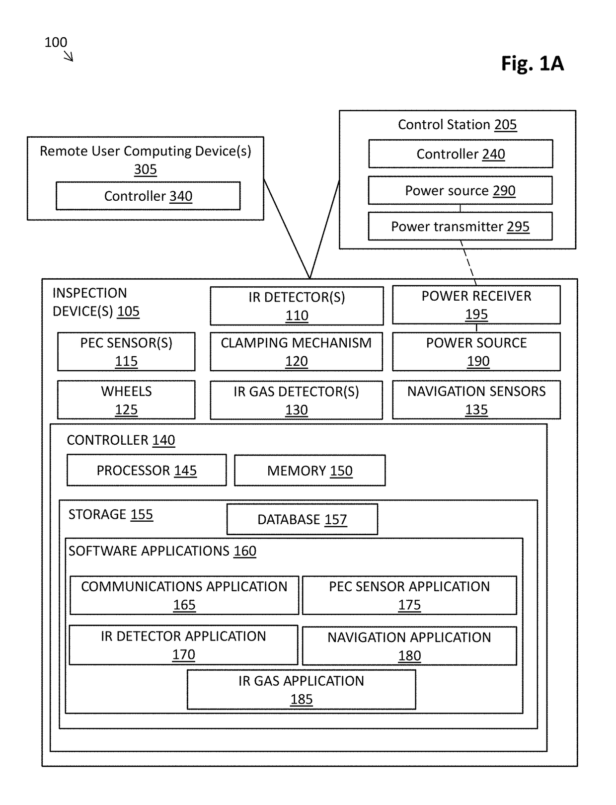
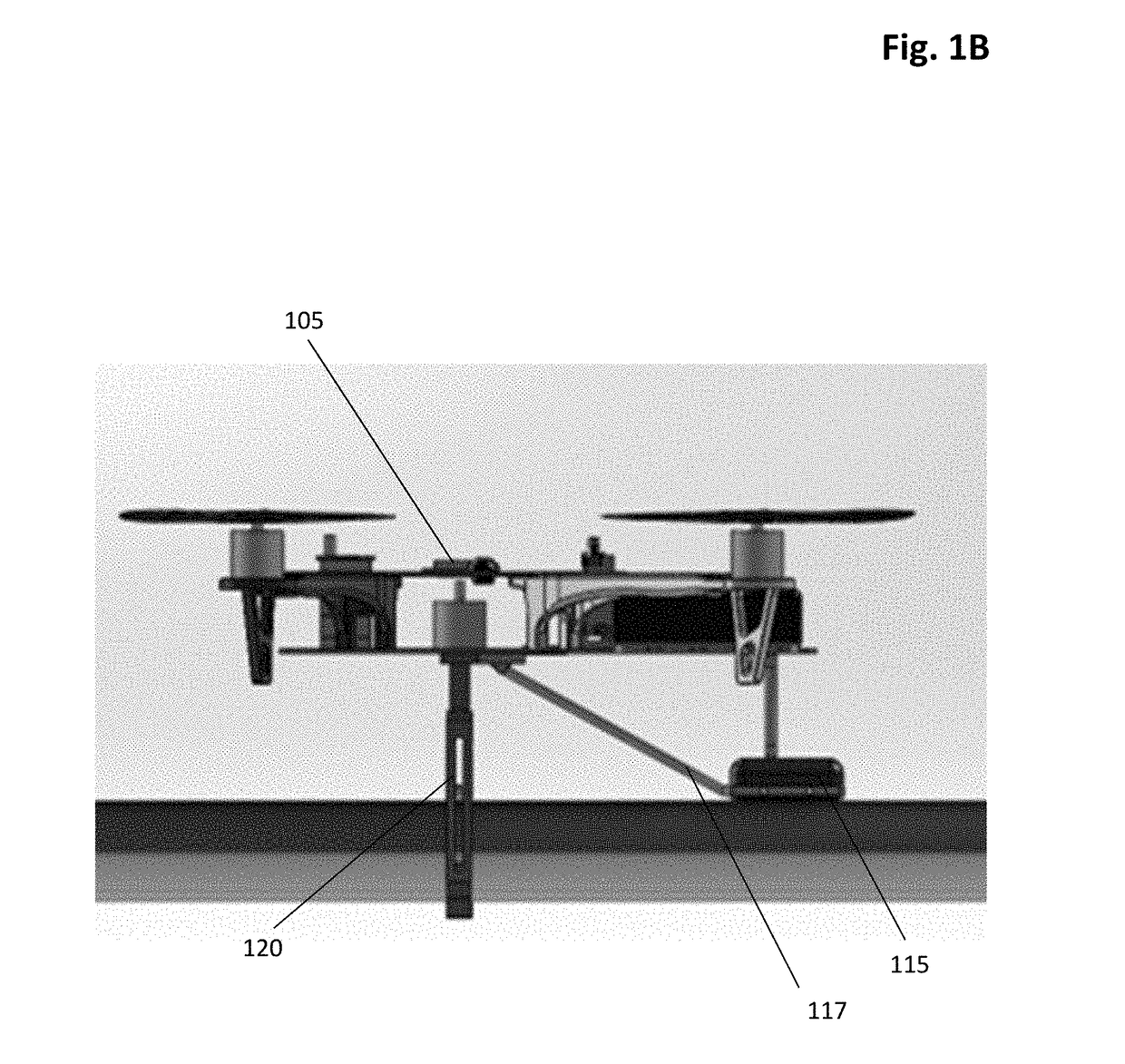
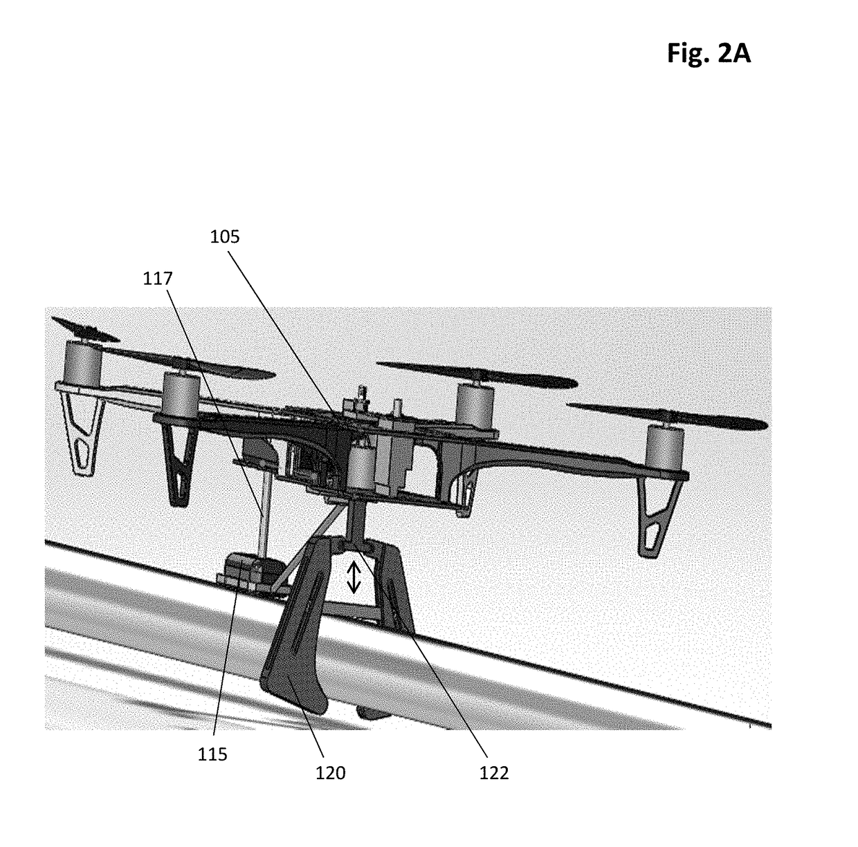
[0023]By way of overview and introduction, the present disclosure details systems and methods for inspection of insulated equipment and detection of corrosion under insulation (CUI) in insulated equipment. Despite the understanding in the field that CUI can cause immense damage to insulated equipment, conventional processes for identifying areas of the equipment damaged by CUI are time-consuming and costly due to the inability to quickly and accurately identify the damaged areas. As such, in an effort to improve the efficiency and cost-effectiveness of inspection, the systems and methods as described herein provide a series of operations in which insulated equipment is assessed for possible CUI damage.

[0024]More specifically, in accordance with at least one embodiment of the present application, a system is provided for inspection of insulated equipment. The system can include one or more inspection devices (e.g., a modular, unmanned aerial vehicle (“UAV”)), each of which can includ...


PUM

PropertyMeasurementUnit
speedsaaaaaaaaaa
speedsaaaaaaaaaa
corrosionaaaaaaaaaa

Abstract

Methods and systems for inspecting insulated equipment for corrosion under insulation are provided. The system includes an autonomous unmanned vehicle having aerial and ground locomotive capabilities. The vehicle includes an infrared detector and a pulsed eddy current sensor. In the method, infrared waves emitted from the equipment are detected along the equipment with the infrared detector. Using the infrared detector, at least one image of an inner surface of the equipment is developed based on the detected infrared waves. At least one area that is susceptible to corrosion is determined based on the at least one image. The susceptible area is inspected with the pulsed eddy current sensor, which induces an eddy current in the inner wall of the equipment. Based on a rate of the decay in strength of the eddy current, it is determined whether corrosion exists at the susceptible area using a processor configured by code.

Description

FIELD OF THE INVENTION[0001]The present invention relates to a system and process for inspecting equipment for corrosion, and, more specifically, relates to nondestructive testing systems and methods for evaluating insulated equipment for corrosion under insulation and to vehicles including unmanned, autonomous, modular vehicles with dual locomotion (e.g., aerial and crawling) capabilities and dual sensory systems.BACKGROUND OF THE INVENTION[0002]Corrosion under insulation (CUI) is a particular type of corrosion that can occur in insulated equipment (e.g., piping) due to ingress of water into the insulated layer and moisture build-up on the external surface of the insulated equipment. Insulated equipment that is exposed to mist and cooling water towers, as well as equipment that is exposed to steam vents can be especially vulnerable to the development of CUI. CUI is difficult to detect in its early stages as its precursor is merely the accumulation of moisture and water patches unde...

Claims


Application Information

Patent Timeline
Patent Type & Authority Patents(United States)
IPC IPC(8): G01N27/90G01N27/00G01N25/72B64C39/02G01J5/10G01J5/00
CPCG01N27/9033B64C39/024G01J5/10G01N27/00G01N25/72G01J2005/0077B64C2201/123G01N21/3504G01N27/90G01N17/02G01N21/954B64U2101/30G01N27/9006
Inventor AMER, AYMANSHEHRI, ALIPARROTT, BRIAN
Owner SAUDI ARABIAN OIL CO
Learn More