
Generating leakage canceling current in electric vehicle charging systems

a technology of electric vehicle and current canceling current, which is applied in the direction of electric variable regulation, process and machine control, instruments, etc., can solve the problems of undesirable leakage current flowing on the ground node, low common mode capacitance of vehicle circuit, and difficult to achieve some vehicle designs, so as to reduce the number of circuit components and complexity, and the effect of easy installation

Active Publication Date: 2018-11-27
MOTIV POWER SYST
View PDF8 Cites 7 Cited by
  • Summary
  • Abstract
  • Description
  • Claims
  • Application Information

AI Technical Summary

Benefits of technology

[0010]In accordance with one novel aspect, the charger module is non-isolated from the electric vehicle charging station and power source. Accordingly, the charger module, the electric vehicle charging station, the circuitry internal to the electric vehicle, and the power source share a common ground. Isolated charger modules that include inductors, transformers, or similar type of magnetic devices are well known in the art. However, such isolated charger modules are expensive and prohibitively costly in some applications. In addition, isolated charger modules tend to be large and difficult to install in some vehicles. The non-isolated charger module, on the other hand, includes no such inductors, transformers, or magnetic devices. The power converter also does not include any inductor, transformer, or magnetic device. No inductor, transformer, or magnetic device is present in a power conversion path of the power converter. No inductor, transformer, or magnetic device is directly coupled to an output node of the power converter. This reduces the number of circuit components and complexity required to manufacture the power converter. As a result, the non-isolated charger module is significantly cheaper to manufacture than traditional isolated charger modules. Moreover, the non-isolated charger module is smaller than traditional isolated charger modules thereby yielding at least one-hundred and seventy watts of output per cubic inch of volume of the charger module.

Problems solved by technology

Electric vehicle charging stations usually must comply with safety regulations and standards because of the hazardous voltage and current levels available at the AC power source to the power circuitry of the electric vehicle.
This requirement limits the common mode capacitance of vehicle circuits to a low value, which can be difficult to achieve for some vehicle designs.
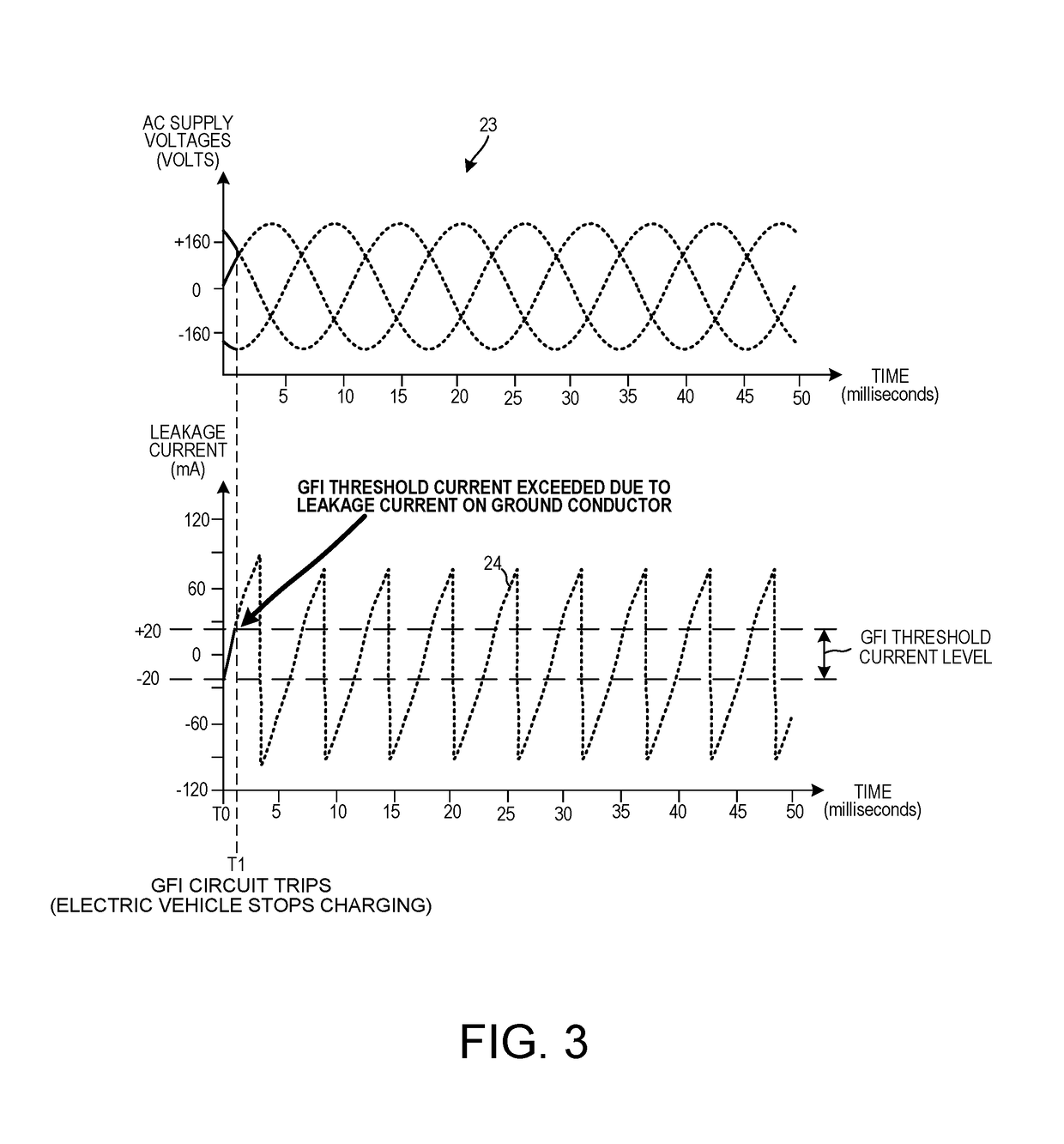
Under certain conditions, the leakage current that flows on the ground node is undesirable.
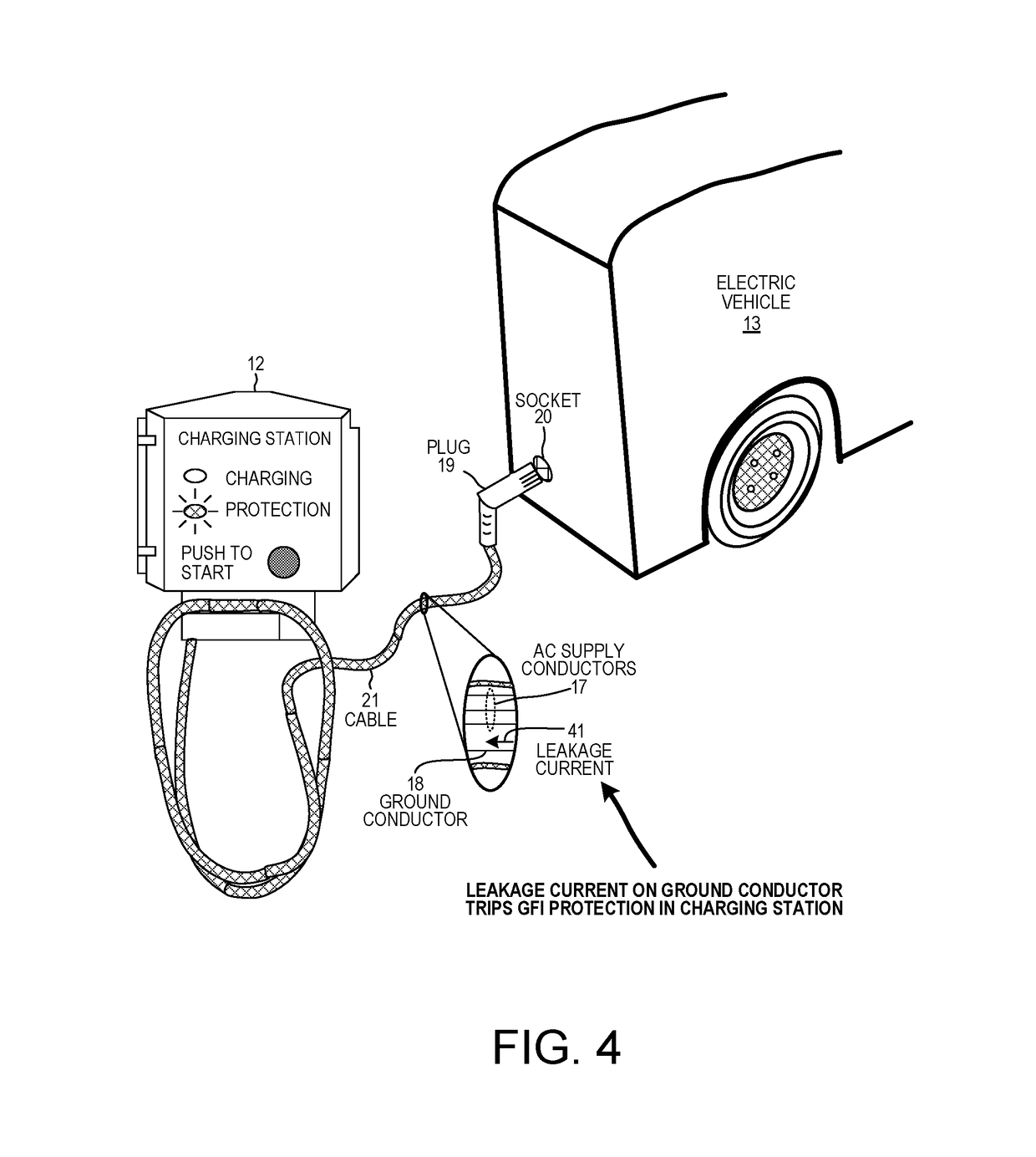
Such flow of leakage current is undesirable because the electric vehicle will not charge if the GFI circuit trips and disables charging.
If a short circuit condition exists, then the GFI circuit will trip and charging operation will be disabled to prevent damage to the electric vehicle circuitry.
The leakage current cancelation circuit will not prevent the GFI circuit from tripping during such a short circuit condition.
However, such isolated charger modules are expensive and prohibitively costly in some applications.
In addition, isolated charger modules tend to be large and difficult to install in some vehicles.

Method used


Image

  • Generating leakage canceling current in electric vehicle charging systems
  • Generating leakage canceling current in electric vehicle charging systems
  • Generating leakage canceling current in electric vehicle charging systems

Examples


Embodiment Construction

[0052]Reference will now be made in detail to some embodiments of the invention, examples of which are illustrated in the accompanying drawings.

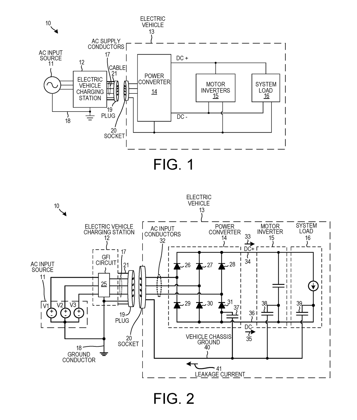
[0053]FIG. 1 is a high level diagram of an electric vehicle charging system 10. Electric vehicle charging system 10 includes an Alternating Current (AC) input source 11, an electric vehicle charging station 12, and an electric vehicle 13. In this example, electric vehicle charging station 12 is a CS-100 electric vehicle charging station available from ClipperCreek, Inc., located at 11850 Kemper Rd. #E, Auburn, Calif. 95603. In another example, electric vehicle charging station 12 is an Evr-Green 400 Electric Vehicle Charging Station available from Leviton Mfg. Company Inc., located at 201 North Service Rd., Melville, N.Y. 11747. The electric vehicle 13 comprises a power converter 14, motor inverters 15, and a system load 16. Many additional components involved in the structure and operation of electric vehicle 13 are excluded for explanatory...


PUM


Abstract

A system includes a power source, a power converter, a leakage current cancelation circuit, a load, and a ground node. The power converter is coupled to the power source and supplies the load. During operation of the power converter, a common mode current flows from the load to the ground node via a leakage capacitance. The leakage current cancelation circuit receives at least one signal indicative of the common mode current and generates a leakage cancelation current that is injected into at least one node of the system. The leakage cancelation current has a magnitude opposite a magnitude of the common mode current. For example, the leakage current cancelation circuit receives supply voltage signals output by the power converter, and generates and supplies the leakage cancelation current onto input nodes of the power converter such that a current level on the ground node is between −3.0 milliamperes and +3.0 milliamperes.

Description

CROSS REFERENCE TO RELATED APPLICATIONS[0001]This application is a continuation of, and claims priority under 35 U.S.C. § 120 from, nonprovisional U.S. patent application Ser. No. 14 / 614,118 entitled “Generating Leakage Canceling Current In Electric Vehicle Charging Systems,” filed on Feb. 4, 2015, now U.S. Pat. No. 9,696,743. application Ser. No. 14 / 614,118 in turn claims the benefit under 35 U.S.C. § 119 of provisional application Ser. No. 62 / 042,696, entitled “Generating Leakage Canceling Current In Electric Vehicle Charging Station System,” filed Aug. 27, 2014. The entire subject matter of the aforementioned patent documents is incorporated herein by reference.TECHNICAL FIELD[0002]The present disclosure relates generally to power systems involving power converters, and more specifically to methods for charging electric vehicles.BACKGROUND INFORMATION[0003]An electric vehicle typically includes energy storage systems that store electrical energy, such as battery packs. Power circ...

Claims


Application Information

Patent Timeline
Patent Type & Authority Patents(United States)
IPC IPC(8): H02J7/00G05F3/02B60L11/18
CPCB60L11/1811G05F3/02B60L3/0069B60L53/22B60L53/20Y02T10/70Y02T10/7072Y02T90/14Y02T90/12
Inventor TREICHLER, WILLIAMCASTELAZ, JAMES MICHAELZULAUF, GRAYSON
Owner MOTIV POWER SYST
Learn More