
Molded and shaped acoustical insulating vehicle panel and method of making the same

a technology of acoustical insulation and a vehicle panel, which is applied in the direction of weaving, transportation and packaging, layered products, etc., can solve the problems of difficult to meet the needs of customers, so as to reduce the cost of the improved panel, the effect of improving the quality and improving the appearan

Active Publication Date: 2018-12-04
L INT IP HLDG LLC
View PDF30 Cites 2 Cited by
  • Summary
  • Abstract
  • Description
  • Claims
  • Application Information

AI Technical Summary

Benefits of technology

The panel provides significant noise abatement, is lightweight, and cost-effective, allowing for reduced component count and weight in vehicles, while maintaining structural integrity and aesthetic appeal.

Problems solved by technology

A large part of the cost and weight is that of the metal parts used in the construction, e.g., body parts, protective and acoustical panels, and the like.
Wheel well shields are a particularly difficult problem in the art, since these shields must not only prevent substantial egress of splashed water from the road into the underbody or engine compartment, but in order to be fully satisfactory must abate road noises occasioned by debris being spun by the tires into the wheel well.
Of notable example of such noise is when an automobile traverses a gravel road, gravel is spun into the wheel wells by the tires and makes a very objectionable noise when the wells are unprotected or protected by shields that do not sufficiently acoustically abate that noise.
These types of solutions were very effective in providing physical protection to the engine compartment and body structures, but were not effective in reducing vehicle noise levels.
Additionally, due to the high stiffness and low damping properties, these shields generate unwanted noise in many situations where debris or water impact the shield and excite the structure so as to cause vibrations.
These unwanted noises often result in ringing or panging sounds as water splashes or road debris impacts the shield.
However, they do not meet current demands for noise abatement.

Method used


Image

  • Molded and shaped acoustical insulating vehicle panel and method of making the same
  • Molded and shaped acoustical insulating vehicle panel and method of making the same

Examples


examples

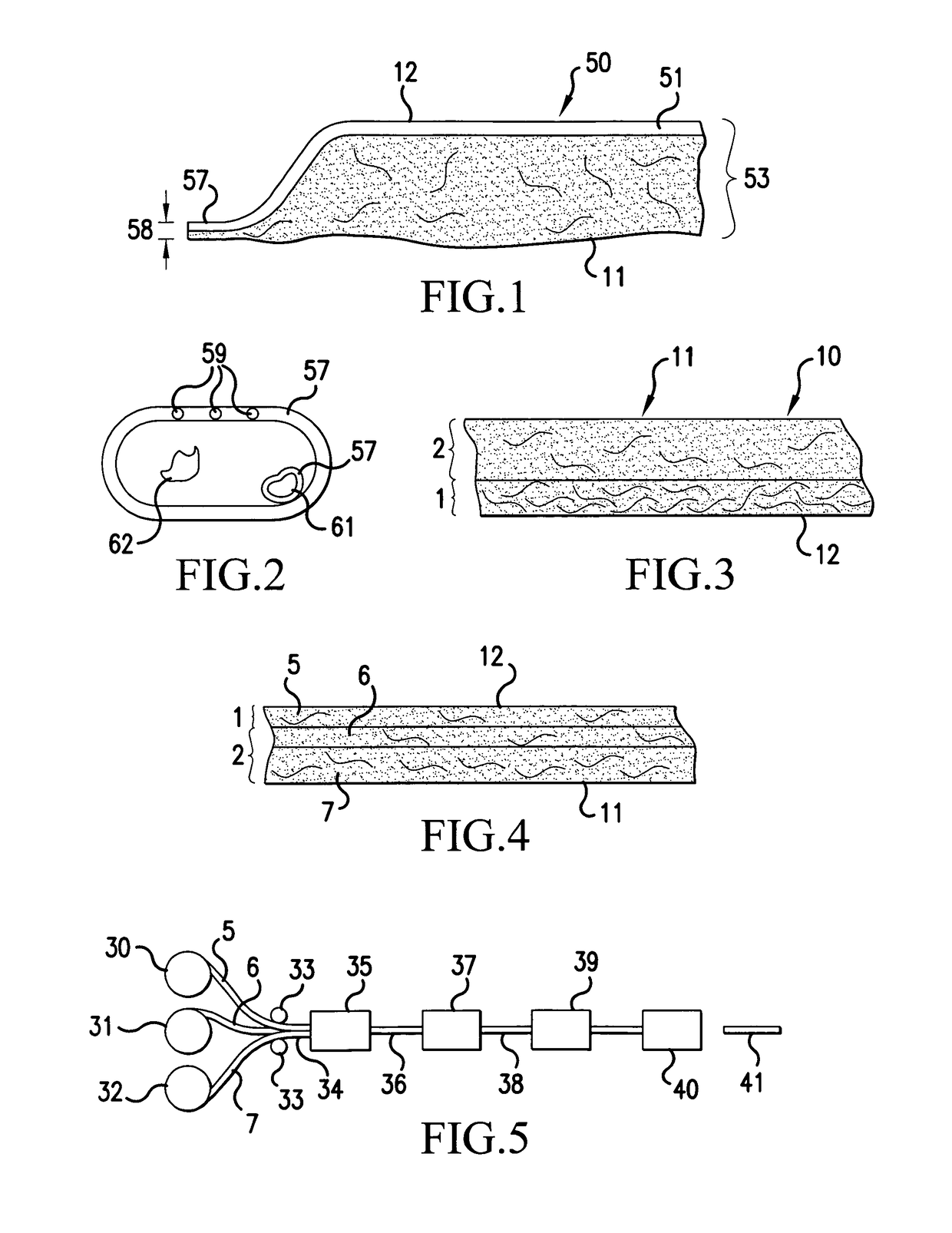
[0051]In this first example, a specific example of a three-layer product that utilizes three individual carding machines will be described in detail.

[0052]The first layer is composed of 2 different polyester fibers. The predominant fiber is a black polyester bicomponent with a sheath melting point of about 230° F. (110° C.). This fiber is 70% of the blend ratio. The second fiber in the first layer is a black polyester staple, and it is 30% of the blend. The two fibers are mixed to the above ratio by weight and then thoroughly opened and blended and introduced into a carding machine. The card produces a web that is carried by the cross-lapper which creates horizontal laps of the carded web. The number of horizontal laps is set so the total weight of the first layer is 7.0 ounces per square yard (237 grams per square meter) in the final needled composite. The first portion of the present invention is comprised entirely of the first carded layer.

[0053]The second carded layer is compose...


PUM

PropertyMeasurementUnit
densityaaaaaaaaaa
densityaaaaaaaaaa
insulation densityaaaaaaaaaa

Abstract

A molded and shaped acoustical insulating vehicle panel having a dry-laid needled fibrous composite composed of a first portion of about 50 to 80 percent meltable binder fibers and about 20 to 50 percent stable fibers and having a second portion of about 20 to 50 percent meltable binder fibers and 50 to 80 percent of staple fibers. The meltable binder fibers are in a molded and resolidified state such that the resolidified binder fibers of the first portion form a substantially continuous, semi-impervious, densified skin integrally associated with and bonded to a surface of the first portion. The molded composite is in such a heat and pressure molded state that the composite has over a predominance of its area a density of from about 12 to 22 lbs. / cubic foot (192 to 352 kg / cubic meter) and the panel is sufficiently rigid as to be self-supporting.

Description

CROSS-REFERENCE TO RELATED APPLICATIONS[0001]This nonprovisional application claims priority under 35 U.S.C. § 119(e) on U.S. Provisional Application No. 60 / 960,402, filed on Sep. 28, 2007, the entirety of which is incorporated herein by reference.BACKGROUND OF THE INVENTION[0002]1. Field of the Invention[0003]The present invention relates to a molded and shaped insulating vehicle panel, particularly to such a panel that is acoustically insulating, and to a method for making that panel. More particularly, the present invention is directed to such panels that are used in assembling automobile and truck vehicles, such as door panels, roof panels, backlight panels and wheel wells, and especially the latter.[0004]2. Description of Background Art[0005]There has been a continued effort in the art to reduce the cost and weight of motor vehicles. A large part of the cost and weight is that of the metal parts used in the construction, e.g., body parts, protective and acoustical panels, and t...

Claims


Application Information

Patent Timeline
Patent Type & Authority Patents(United States)
IPC IPC(8): B60R13/08B32B5/14D04H13/00D04H1/541D04H1/485D04H1/558B32B5/06B32B3/26B32B5/26
CPCB60R13/0861B32B3/26B32B5/06B32B5/14B32B5/26B60R13/0815D04H1/541D04H1/558D04H13/005D04H1/485Y10T442/692Y10T442/667Y10T442/688D04H1/5412D04H1/5418B60Y2410/12
Inventor BORCHARDT, STEVENJARRARD, BRIAN
Owner L INT IP HLDG LLC
Learn More