Touch probe for CMM including digital signal communication

a technology of digital signal communication and touch probe, which is applied in the field of precision metrology, can solve the problems of increased size, increased number of wires to the touch probe, and trade-offs between all elements, and achieve the effect of increasing the functionality of the touch probe and/or ease-of-us

Active Publication Date: 2018-12-04
MITUTOYO CORP
View PDF23 Cites 11 Cited by
  • Summary
  • Abstract
  • Description
  • Claims
  • Application Information

AI Technical Summary

Benefits of technology

[0010]In contrast to the prior art, disclosed herein is a configuration for a touch probe that includes a unique combination of features which allows useful digital signal processing and control functions in a touch probe, as well as reliable trigger signal transmission and two-way digital signal communication with a host CMM, without the need for an associated size increase, and using only two electrical connections between the touch probe and the host CMM. By way of example, and not by way of limitation, such a configuration may allow increased probe functionality and / or ease-of-use, as well as a “retrofit ability” for using the touch probe with existing host machine hardware.

Problems solved by technology

The performance levels and miniaturization currently demanded in touch probe bodies has typically forced tradeoffs between all elements combined in such devices, particularly when adding a new feature or capability.
For example, increased signal processing internal to a touch probe, and / or increased communication complexity between a touch probe and a host machine, has generally contributed to increased size, an increased number of wires to the touch probe, and / or limited “retrofit ability” for using the touch probe with existing host machine hardware.
One factor hindering improved solutions to these problems has been that it has proved difficult to provide configurations that achieve similar high accuracy measurements (e.g., micron or submicron level repeatability), internal signal processing, and digital signal communication with external devices, in a compact configuration (e.g., on the order of 12-15 millimeter diameter in some implementations, or about the size of a human “pinky” finger).

Method used


Image

  • Touch probe for CMM including digital signal communication
  • Touch probe for CMM including digital signal communication
  • Touch probe for CMM including digital signal communication

Examples


Embodiment Construction

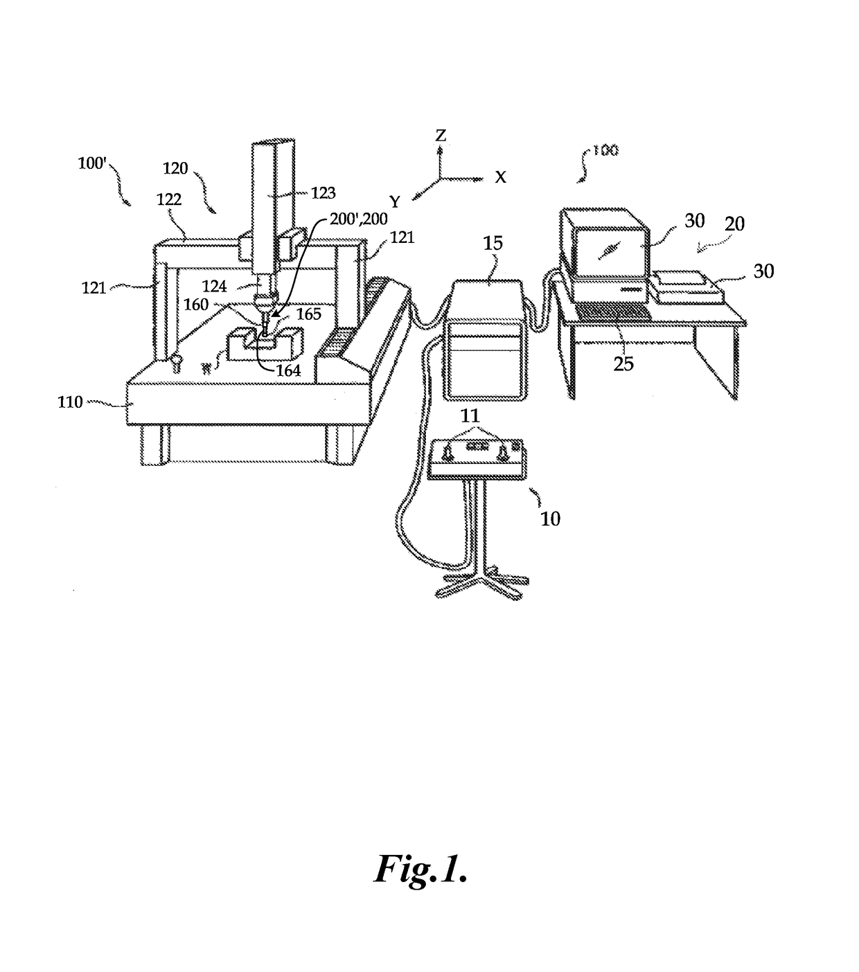
[0019]FIG. 1 is a diagram showing various components of a measuring system 100 including a CMM 100′ utilizing a touch probe 200′ such as that disclosed herein. Coordinate measuring machines (CMMs) are known in the art, for example, in U.S. Pat. Appl. Publ. No. 2011 / 0192044, to Usui, which is hereby incorporated by reference in its entirety. An arrangement of a CMM is illustrated schematically in FIG. 1, showing a measuring system 100 including a CMM 100′, which uses a touch probe 200′. The touch probe 200′ may include a probe body 200. The measuring system 100 includes an operating unit 10, a motion controller 15 that controls movements of the CMM 100′, a host computer 20 and the CMM 100′. The operating unit 10 is coupled to the motion controller 15 and may include joysticks 11 for manually operating the CMM 100′. The host computer 20 is coupled to the motion controller 15 and operates the CMM 100′ and processes measurement data for a workpiece W according to known methods. The host...


PUM


Abstract

A compact CMM touch probe may include internal digital processing, a regulated power circuit, a trigger signal generating circuit, an interface connector limited to two electrical connections, and a differential signal configuration that inputs and outputs differential digital communication signals (including touch trigger signals) through the two connections, superimposed on a CMM supply voltage connected to them from the CMM. A specialized supply isolation circuit is configured in combination with various probe components and operating parameters, to couple the regulated power supply circuit to the CMM supply voltage at the two connections, while isolating it from loading the differential digital signals, which are AC coupled to the two connections. The differential digital signals may normally comprise touch trigger signals, and intermittent control and data signals, during separate respective time periods. In various embodiments, at least a majority of the differential digital signals are formatted using a DC-balanced encoding scheme.

Description

BACKGROUND[0001]Technical Field[0002]This disclosure relates to precision metrology, and more particularly to touch probes used in coordinate measurement systems.[0003]Description of the Related Art[0004]Certain coordinate measurement systems, e.g., one-dimensional or three-dimensional measurement systems, such as coordinate measuring machines (CMMs), may obtain measurements of a workpiece using a touch probe configured to detect when a stylus of the touch probe contacts a workpiece. Touch probes use various types of displacement sensors to sense deflection of the touch probe stylus for an indication that it has contacted a workpiece.[0005]An exemplary prior art CMM utilizing a touch probe is described in U.S. Pat. No. 5,526,576 (the '576 patent), which is hereby incorporated herein by reference in its entirety. The '576 patent discloses a movement mechanism comprising multiple drives for moving the touch probe, an associated electronic system including a CANBUS digital communicatio...

Claims


Application Information

Patent Timeline
Patent Type & Authority Patents(United States)
IPC IPC(8): G01B5/016G01B5/012
CPCG01B5/012G01B5/016G01B7/002G01B7/012
Inventor JANSSON, BJORN ERIK BERTIL
Owner MITUTOYO CORP
Why Eureka
Try Eureka