
Antenna measuring station

a technology for measuring stations and antennas, applied in the direction of transmission monitoring, receiver monitoring, line-transmission, etc., can solve the problems of disadvantageous mm wave, low range, and high cost of antenna measurements, and achieve the effects of small tolerances, increased accuracy, and compensating polarization losses

Active Publication Date: 2018-12-11
FRAUNHOFER GESELLSCHAFT ZUR FOERDERUNG DER ANGEWANDTEN FORSCHUNG EV +1
View PDF11 Cites 0 Cited by
  • Summary
  • Abstract
  • Description
  • Claims
  • Application Information

AI Technical Summary

Benefits of technology

This patent describes an improved antenna measuring station that can accurately measure the performance of a reference antenna and a new antenna under test without causing any polarization losses. This is achieved by controlling the switching matrix to rotate the polarization of the reference antenna and the antenna under test by 90 degrees, and by using a laser measuring device to determine the spatial distance and angle of the reference antenna relative to the antenna under test. Additionally, the control device can compensate for polarization losses by determining the orientation of the reference antenna relative to the antenna under test. This improved system allows for more precise and accurate measurement of antenna performance.

Problems solved by technology

However, some physical characteristics of the mm waves are disadvantageous, such as low range due to high attenuation and reflection at many solid and liquid materials.
The central issues in these technical developments are the antennas for optimum transmission and reception of mm and THz waves.
The antenna measurements are currently very time-consuming and have to be performed by experienced high-frequency (HF) specialists.
These expensive shielded rooms and the need for highly qualified HF specialists for performing the measurements as well as the high time effort for performing the measurements are obstacles for the development of mm and THz wave antennas and the quality control of these antennas in production.
However, high effort is needed to realize such free-field conditions artificially, namely by providing a so-called an anechoic room.

Method used


Image

  • Antenna measuring station
  • Antenna measuring station
  • Antenna measuring station

Examples


Embodiment Construction

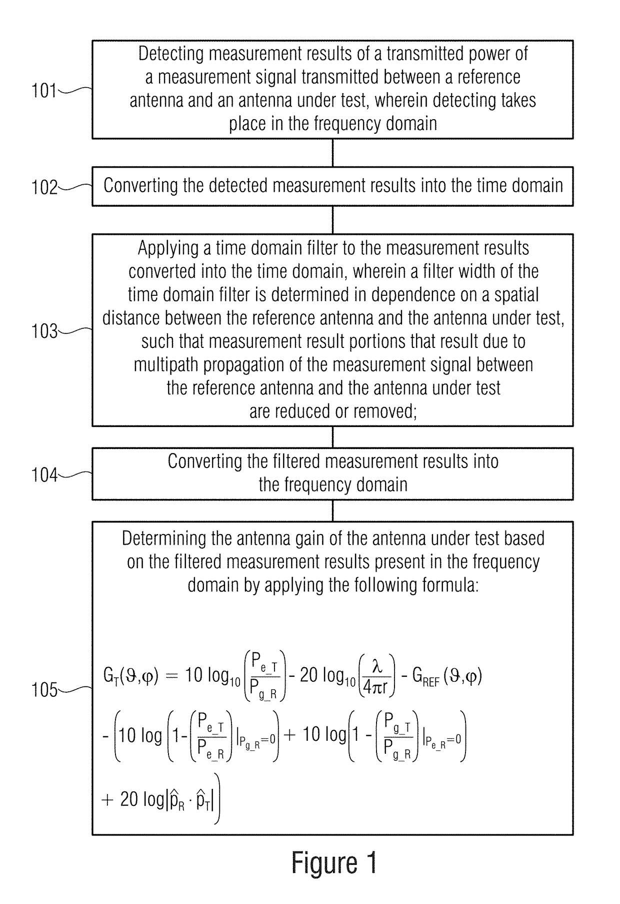
[0090]First, the inventive method will be described with reference to FIG. 1.

[0091]In block 101, measurement results of a transmitted power of a measurement signal transmitted between a reference antenna and an antenna under test are detected, wherein detecting takes place in the frequency domain.

[0092]In block 102, detected measurement results are converted into the time domain.

[0093]In block 103, a time-domain filter is applied to the measurement results converted into the time domain, wherein a filter width of the time-domain filter is determined in dependence on a spatial distance between the reference antenna and the antenna under test, such that measurement result portions resulting due to multipath propagation of the measurement signal between the reference antenna and the antenna under test are reduced or removed.

[0094]In block 104, the filtered measurement results are converted into the frequency domain.

[0095]In block 105, the antenna gain GT(ϑ,φ) of the antenna under test ...


PUM


Abstract

An apparatus and a method for determining an antenna characteristic of an antenna under test in free space is disclosed. Measurement results of a transmitted power of a measurement signal transmitted between the reference antenna and an antenna under test are detected, wherein detecting takes place in the frequency domain. The detected measurement results are transformed into the time domain and a time-domain filter is applied to the measurement results converted into the time domain. A filter width of the time-domain filter is determined in dependence on a spatial distance between the reference antenna and the antenna under test. Measurement result portions that result due to a multipath propagation of the measurement signal between the reference antenna and the antenna under test are reduced or removed.

Description

CROSS-REFERENCE TO RELATED APPLICATIONS[0001]This application claims priority from German Patent Application No. 10 2016 218 891.7, which was filed on Sep. 29, 2016, and is incorporated herein in its entirety by reference.[0002]The invention relates to a method for determining an antenna characteristic of an antenna under test in free space having the features of claim 1, an apparatus for determining an antenna characteristic of an antenna under test in free space having the features of claim 7 as well as an antenna measuring station for determining an antenna characteristic of an antenna under test in free space (non-reflective) having the features of claim 14.BACKGROUND OF THE INVENTION[0003]The economic usage of millimeter (mm) and terahertz (THz) waves has significantly increased in recent years. All over the world, the practical usage of mm and THz waves for communication and radar applications is intensively worked on. This frequency range has many important advantages. The mo...

Claims


Application Information

Patent Timeline
Patent Type & Authority Patents(United States)
IPC IPC(8): H04B17/12H04W24/08H04B3/23G01R29/10H04B17/318H04B17/10H04B17/13H04B17/14H04B17/27
CPCG01R29/10H04B17/102H04B17/12H04B17/318H04B17/14H04B17/27H04B17/13
Inventor NDIP, IVANGROSSER, VOLKERTSCHOBAN, CHRISTIANCURRAN, BRIANHUHN, MAXLANG, KLAUS-DIETER
Owner FRAUNHOFER GESELLSCHAFT ZUR FOERDERUNG DER ANGEWANDTEN FORSCHUNG EV
Learn More