
Planar waveguide grating devices having controlled polarization dependent sensitivity and method of manufacturing thereof

a technology waveguide grating, which is applied in the direction of optics, instruments, and light guides, can solve the problems of polarization dependent loss (pdl), cumbersome techniques, and difference in diffraction efficiency, and achieves good repeatability, process controllability, and reduce the effect of polarization dependent loss of waveguide grating devices

Inactive Publication Date: 2008-09-02
KARUNARATNE B HIPPOLA +3
View PDF4 Cites 0 Cited by
  • Summary
  • Abstract
  • Description
  • Claims
  • Application Information

AI Technical Summary

Benefits of technology

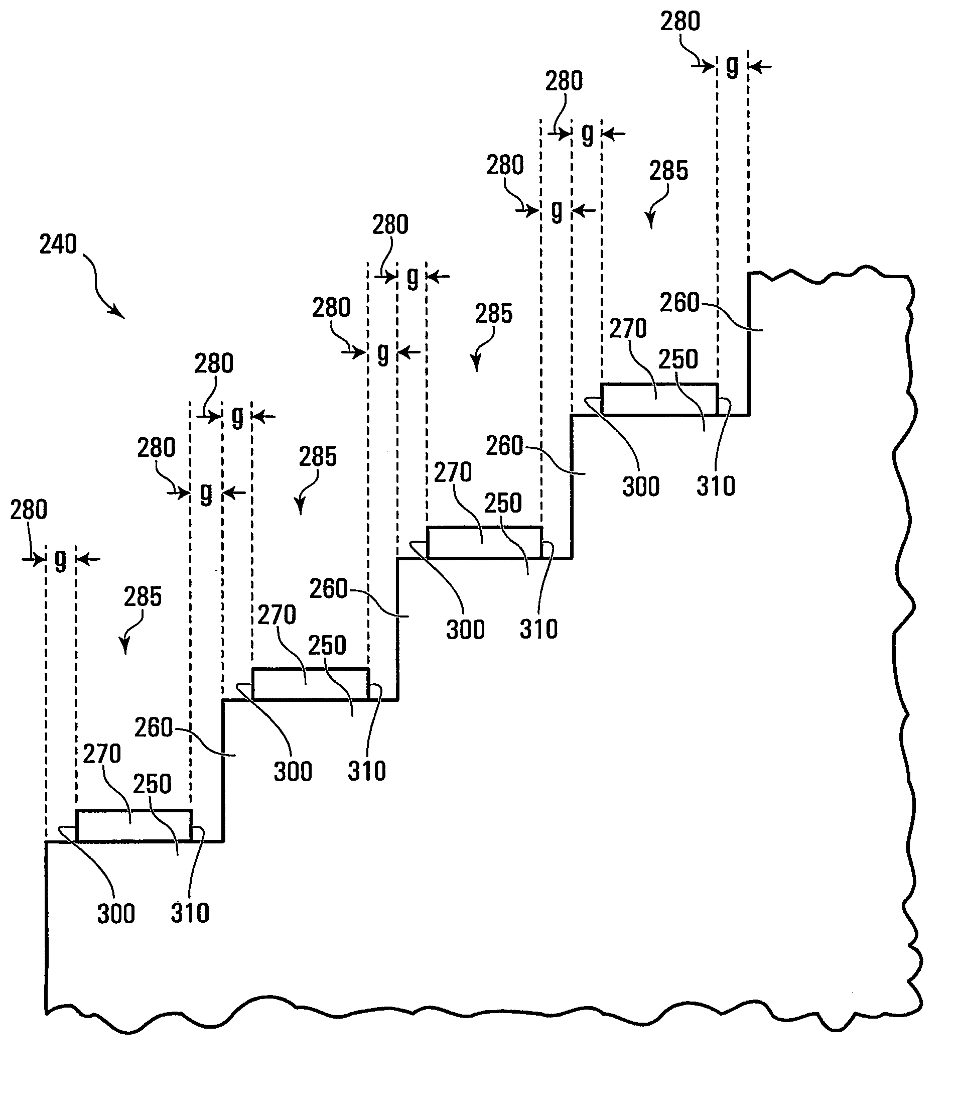
"The invention provides a diffraction grating with a plurality of grooves in a substrate, each groove having a surface that serves as a reflective facet. The reflective facet is coated with a conductive material, such as aluminum, gold, or silver. The grating has a high refractive index surrounded by a lower refractive index material. The grating can be formed using a lithography technique to pattern the metal only on the reflective facet, leaving no metal on the sidewalls. The reflective facet is embedded within an optical waveguide. The grating can be used in optical devices to diffract light. The technical effects of the invention include improved diffraction efficiency, reduced size of the grating, and improved patterning accuracy."

Problems solved by technology

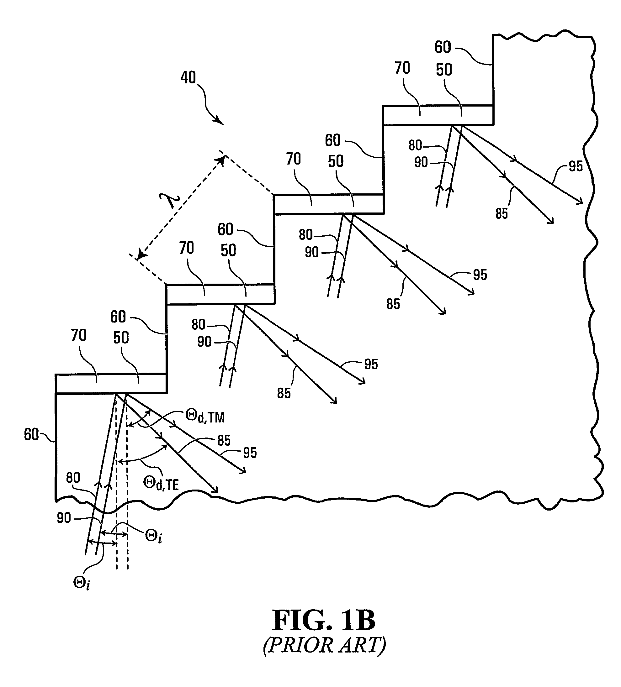
This difference in diffraction efficiency with reference to polarization state leads to Polarization Dependent Loss (PDL).
Assuming that selective removal of metal from non-reflective facets is employed, such techniques are likely to be cumbersome (because selectivity between the reflecting and non-reflective facets is hard to ensure), especially if the grating is concave as in the case of a Rowland circle design.
In reality, such techniques may not be able to remove all the metal from the non-reflective facets leading to non-uniform metal coverage and hence uncontrolled wavelength dependent PDL (Polarization Dependent Loss) or PDλ (Polarization Dependent wavelength shift).
Finally, such techniques cannot leave a predetermined degree of metal coverage on reflective facets.

Method used


Image

  • Planar waveguide grating devices having controlled polarization dependent sensitivity and method of manufacturing thereof
  • Planar waveguide grating devices having controlled polarization dependent sensitivity and method of manufacturing thereof
  • Planar waveguide grating devices having controlled polarization dependent sensitivity and method of manufacturing thereof

Examples


Embodiment Construction

[0059]Planar waveguide diffraction gratings with periodic structures have immense potential for applications in many fields including optical telecommunications, medical and pharmaceutical research, astronomy, chemical sensing, biological sciences, environmental sciences etc.

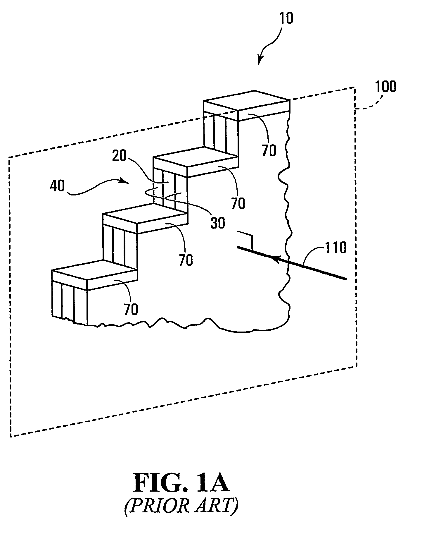
[0060]Referring to FIG. 1A, shown is a perspective view of a portion of a conventional planar waveguide having an Echelle grating based diffraction grating. The planar waveguide is generally indicated by 10 and has a high index layer 20 between layers 30 of lower refractive index with indices chosen to guide and transmit light within the high index layer 20. The planar waveguide 10 has an Echelle grating generally indicated by 40. The Echelle grating is clearly shown in FIG. 1B having metallized reflective facets 50 as well as non-reflective facets 60. The metallized reflective facets 50 each have a metallic coating 70. One of the problems with such gratings is reducing Polarization Dependent Loss (PDL) to an ac...


PUM


Abstract

Diffraction gratings are formed from grooves each having a reflective facet and a non-reflective facet. The net reflection of TE (Transverse Electric) and TM (Transverse Magnetic) polarizations from the grating structure is traded off against the polarization dependent reflection, by controlling the degree of metallization of the reflective facet and by ensuring that there is no metallization of non-reflective sidewalls. other diffraction gratings are manufactured from trenches etched perpendicular to a waveguide. The trenches are metallized and back-filled with a filling material having a refractive index matched to that of the waveguide. The gratings essentially have no non-reflecting sidewalls with insignificant polarization influence from side walls.

Description

CROSS-REFERENCE TO RELATED APPLICATIONS[0001]The present application is based on and claims the benefit of International (PCT) Application Serial No. PCT / CA03 / 001300, filed on Aug. 26, 2003, which claims priority from U.S. Provisional Patent Application Ser. No. 60 / 405,730, filed on Aug. 26, 2002. The entire contents of each of these applications is incorporated herein by reference.FIELD OF THE INVENTION[0002]The invention relates to diffraction gratings with metallized facets.BACKGROUND OF THE INVENTION[0003]In diffraction gratings such as Echelle gratings having metallized facets with both non-reflective facets and reflective facets being metallized, the diffraction efficiency can be substantially different for light polarized parallel to the edges of the facet versus perpendicular to the edges of the facet. In planar waveguide based diffraction gratings, the gratings are created by etching sidewalls perpendicular to the plane of a waveguiding slab, and the facets are often metall...

Claims


Application Information

Patent Timeline
Patent Type & Authority Patents(United States)
IPC IPC(8): G02B5/18G02B5/32G02B6/34
CPCG02B5/1857G02B6/124G02B5/32G02B6/29325
Inventor BALAKRISHNAN, ASHOKDOSSOU, KOKOUPACKIRISAMY, MUTHUKUMARAN
Owner KARUNARATNE B HIPPOLA
Learn More