
Steam generator coolant header with U-shaped tubes of a horizontal heat-exchange bundle and methods of its manufacture

a technology of heat exchange bundle and steam generator, which is applied in the direction of steam generation using hot heat carriers, lighting and heating apparatus, greenhouse gas reduction, etc., can solve the problems of limiting the number of heat exchange tubes, labor-consuming and complex operation, and the most complicated steam generator assembly, so as to increase the filling level of steam generator heat exchange tubes, maintain header strength, and tighten processability

Inactive Publication Date: 2019-01-15
EXPERIMENTAL & DESIGN ORG GIDROPRESS AWARDED THE ORDER OF THE RED BANNER OF LABOUR & CZSR ORDER OF LABOUR
View PDF11 Cites 0 Cited by
  • Summary
  • Abstract
  • Description
  • Claims
  • Application Information

AI Technical Summary

Benefits of technology

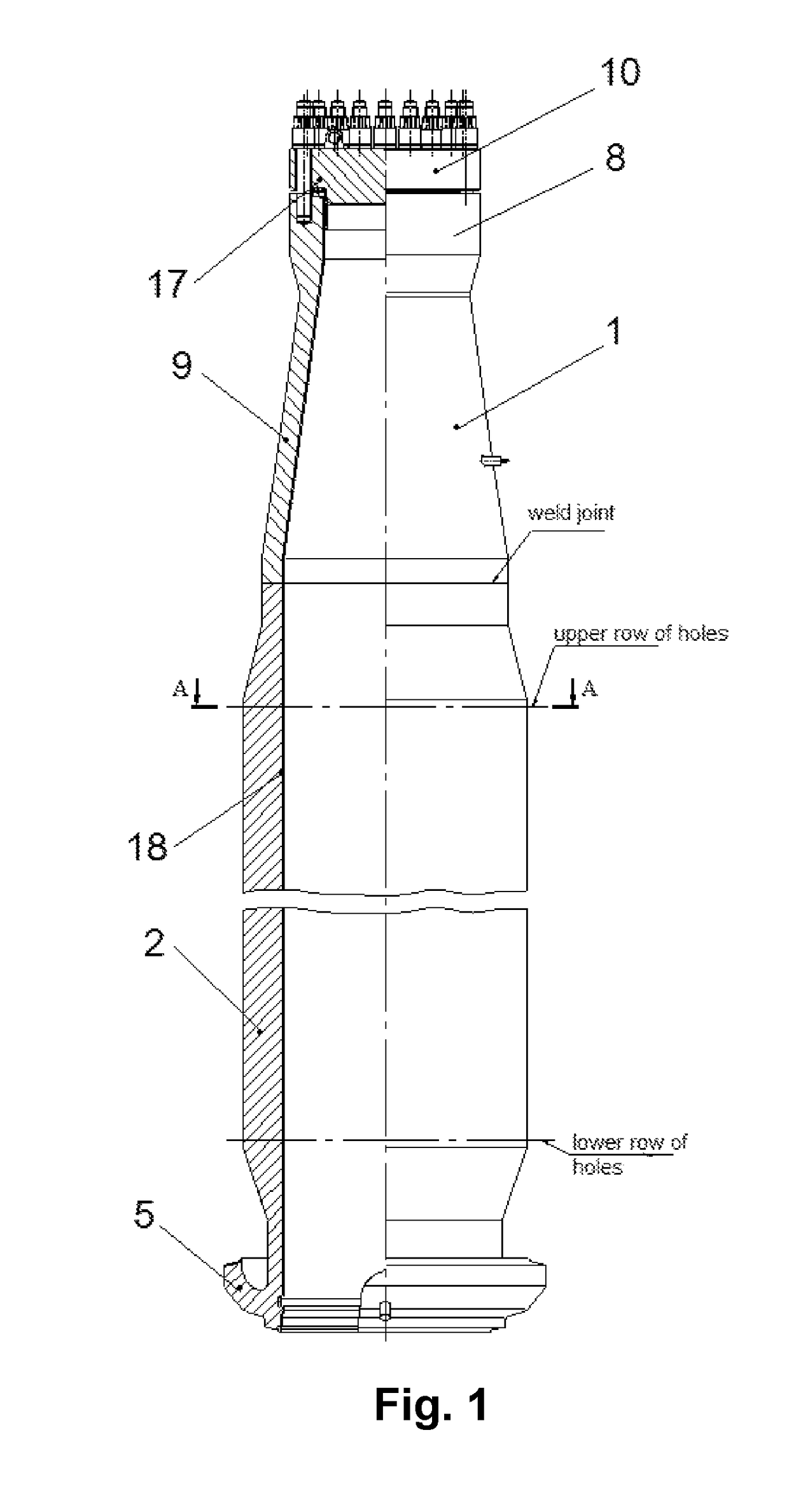
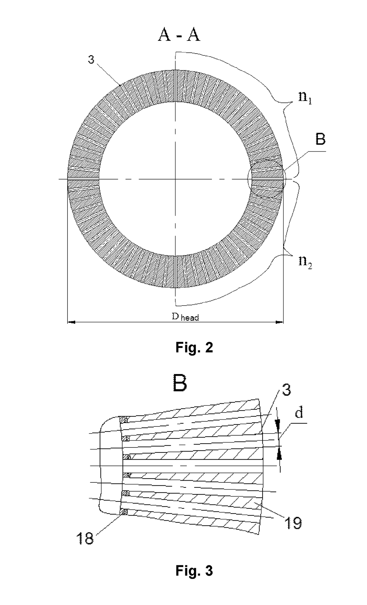
This patent describes a new design for a horizontal steam generator that increases the heat-exchange tube filling level while maintaining the strength and tightness of the heat-exchange tube fastening in the header. The invention also includes a coolant header with a perforated section for efficient tube insertion, a flange connection with an expanded graphite gasket for improved coolant header performance, and the ability to perform eddy current testing on the heat-exchange tube integrity and connection quality. The claimed invention allows for optimal selection of the coolant header outer diameter.

Problems solved by technology

In its turn, connection of a primary circuit coolant header with a heat-exchange tube bundle is the most complicated steam generator assembly for manufacture.
Main problems that can arise during steam generator operation are related to provision of structural integrity of flange connectors and structural integrity of primary circuit coolant headers.
The most labor-consuming and complex operation during steam generator manufacture, from the technological point of view, is the connection of a heat-exchange tube bundle to primary circuit coolant headers involving drilling a large number of closely spaced deep through holes on a limited area of the header side wall followed by leak-tight insertion of heat-exchange tubes in the same.
A large number of closely spaced deep through holes reduces the strength of the header, thus, limiting the number of heat-exchange tubes that can be placed in the steam generator with the specified side wall thickness, and if the number of heat-exchange tubes, a significant increase of the header side wall thickness is required.
The method described is rather labor-consuming and relates only to one operation of heat-exchange tube fastening in the header, and does not cover the full VVER NPP horizontal steam generator primary circuit coolant header manufacture and assembly process.
The said spacing range for heat-exchange tube installation is applicable, without limitation, to tight arrangement of heat-exchange bundle tubes, however the issue of heat-exchange tube positioning in a coolant header in case of the said tight arrangement of the heat-exchange bundle remains unsolved.
That is, if tight arrangement of heat-exchange tubes is used with horizontal spacing 1.44·d and vertical spacing 1.35·d according to this utility model, coolant header perforated section strength and ease of insertion of heat-exchange tubes into the header during creation of heat-exchange bundle banks are not guaranteed.

Method used


Image

  • Steam generator coolant header with U-shaped tubes of a horizontal heat-exchange bundle and methods of its manufacture
  • Steam generator coolant header with U-shaped tubes of a horizontal heat-exchange bundle and methods of its manufacture
  • Steam generator coolant header with U-shaped tubes of a horizontal heat-exchange bundle and methods of its manufacture

Examples


Embodiment Construction

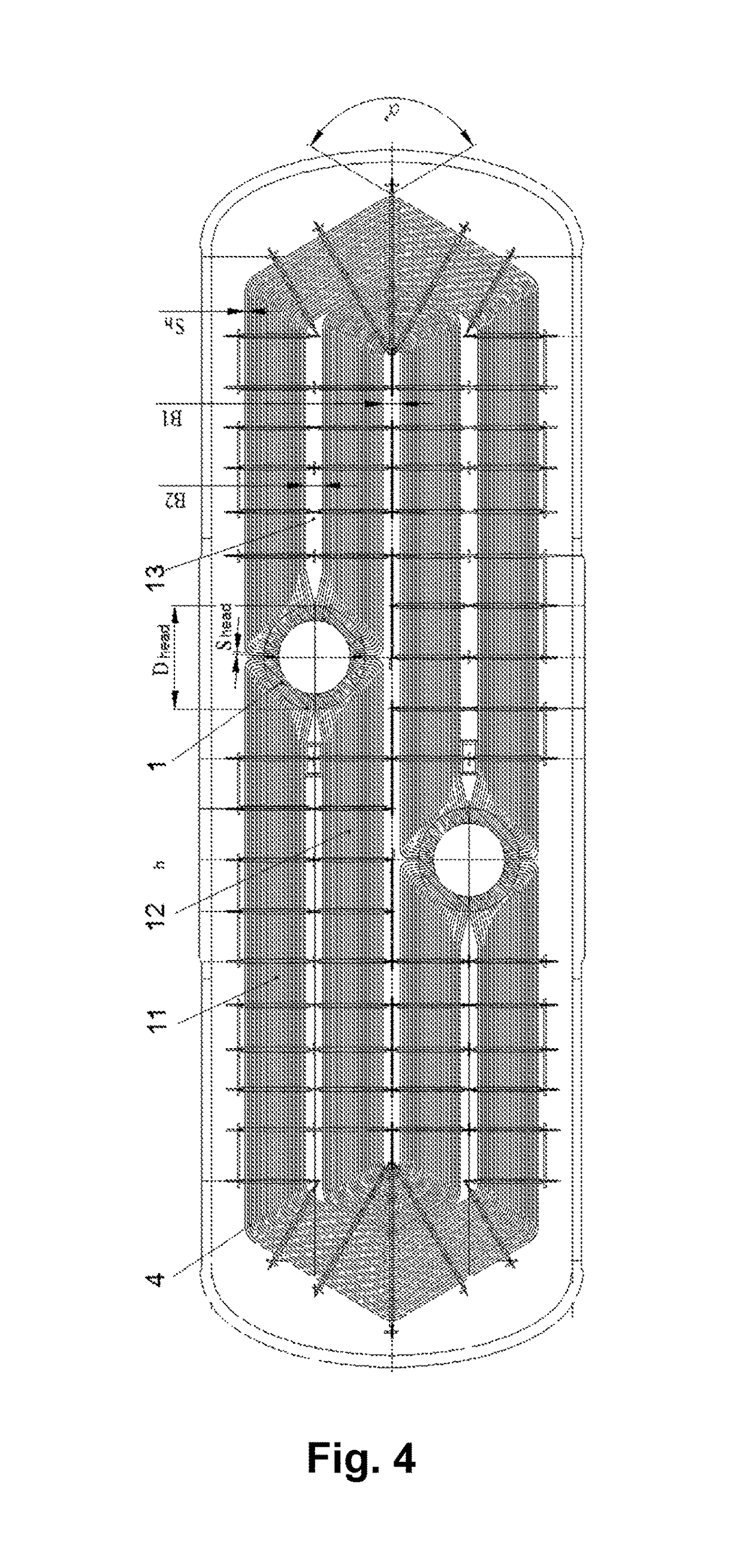
[0068]A steam generator is manufactured with in-line arrangement of tubes. The horizontal spacing between heat-exchange bundle tubes is Sh=27 mm. To form a heat-exchange bundle, Ø18 mm heat-exchange tubes are used. The minimum bend radius of tubes is Rb=120 mm. Number of heat-exchange tubes in a horizontal row of each bank is n1=n2=44. The width of tunnels between tube banks is B1=B2=220 mm.

[0069]Dmin=·[(d+5.5)·(n1+n2)π+100]=1517⁢⁢mm,⁢Dmax=2·[2·(n1-1)·SΓ+22·B2-24·(n1+n2)·SΓ-RΓ·tg⁡(π8)+100]=1987⁢⁢mm.

[0070]If coolant header diameter D is less than 1517 mm, for instance, 1500 mm, horizontal spacing of tubes along the outer header surface will be:

[0071]S=π·D2·(n1+n2)=π·15002·(44+44)=26.78⁢⁢mm

[0072]In case of design pressure values specific to the primary circuit equipment of NPPs with VVER reactors, the header thickness will be 205 mm.

[0073]Therefore, the inter-tubular horizontal spacing along the inner header surface will be

[0074]Sin=S·DD+2·205=21⁢⁢mm,

and the gap between the tubes with...


PUM

PropertyMeasurementUnit
distanceaaaaaaaaaa
bend radiiaaaaaaaaaa

Abstract

This invention relates to electric power industry, and can be used in horizontal steam generators for nuclear power plants (NPP) with a water-water energetic reactor (VVER). We claim a steam generator primary circuit coolant header with U-shaped tubes of a horizontal heat-exchange bundle designed as a thick-wall welded vessel with a perforated central cylindrical part designed so as to allow installation and fastening of a U-shaped heat-exchange tube bundle in the same, wherein the tubes are grouped into banks and separated by vertical inter-tubular tunnels, a lower cylindrical part designed so as to allow welded connection with the steam generator vessel connection pipe, and an upper cylindrical part with a conical adapter to the flange connection of the manhole with a lid, wherein primary circuit header outer diameter Dhead in the central part is selected based on formula.The technical result of the invention involves assurance of strength of the header wall bridges between holes for fastening of heat-exchange tubes and leaktightness of heat-exchange tube connections with the header assuming that the outer surface of the perforated header part is more efficiently (fully) used for tubing.

Description

CROSS-REFERENCE TO RELATED APPLICATIONS[0001]This application is a US 371 Application from PCT / RU2015 / 000787 filed Nov. 16, 2015, which claims priority to Russia Application 2014150428 filed Dec. 12, 2014, the technical disclosures of which are hereby incorporated herein by reference.FIELD OF THE INVENTION[0002]This invention relates to electric power industry, and can be used in horizontal steam generators for nuclear power plants (NPP) with a water-water energetic reactor (VVER).BACKGROUND OF THE INVENTION[0003]A steam generator is an essential component of reactor plant primary circuit. In its turn, connection of a primary circuit coolant header with a heat-exchange tube bundle is the most complicated steam generator assembly for manufacture. High inter-circuit density requirements are imposed on this assembly. That means that the coolant header connection assembly design shall exclude the possibility of damage of heat-transferring and other components, if their loss of tightness...

Claims


Application Information

Patent Timeline
Patent Type & Authority Patents(United States)
IPC IPC(8): F22B1/02F22B29/06B23P15/26F28F1/00
CPCF22B1/023B23P15/26F28F1/00F22B29/064F22B1/02F22B37/22G21D1/006Y02E30/30Y02E30/00F22B37/02F28D7/16F28F9/0132F28D2021/0064
Inventor LAKHOV, DMITRIY ALEKSANDROVICHSAFRONOV, ALEKSEY VLADIMIROVICHKONYUSHKOV, ALEKSANDR GRIGOREVICHALEKSEEV, DIMITRIY EVGENEVICHGERONTIEV, ALEKSANDR EVEGENEVICH
Owner EXPERIMENTAL & DESIGN ORG GIDROPRESS AWARDED THE ORDER OF THE RED BANNER OF LABOUR & CZSR ORDER OF LABOUR
Learn More