Conveying device

a technology of conveying device and rubber member, which is applied in the direction of transportation and packaging, metal working apparatus, and other domestic objects, can solve the problems of generating cut rubber, difficult to convey extruded bead filler to a molding machine while maintaining its curvature, and extremely difficult to form bead filler while forming, so as to achieve accurate cutting of rubber members

Inactive Publication Date: 2019-01-22
TOYO TIRE & RUBBER CO LTD
View PDF26 Cites 0 Cited by
  • Summary
  • Abstract
  • Description
  • Claims
  • Application Information

AI Technical Summary

Benefits of technology

[0015]According to the conveying device of the present invention, the plurality of rollers are spirally arranged around the support to constitute the spiral conveying path. The plurality of rollers rotate while supporting the lower surface of the rubber member extruded from the extrusion device. Accordingly, the rubber member can be conveyed along the conveying path. The rubber member extruded in the curved state is conveyed along the spiral conveying path. Accordingly, the rubber member can be conveyed while maintaining its curvature. Each of the rollers has such a shape that its outer diameter increases from one end to the other end in the axial direction, and the one end is rotatably fixed to the support. Thus, a gap between adjacent rollers can be narrowed. Further, since the plurality of rollers respectively have the drive rollers, it is possible to reliably convey the rubber member. Accordingly, it is possible to appropriately convey the rubber member while maintaining its curvature.
[0017]According to this configuration, it is possible to convey the rubber member while maintaining its curvature and to cut the rubber member into a desired length.
[0019]According to this configuration, since the rubber member can be fixed at the upstream and the downstream of the cutting unit in the conveying direction, it is possible to accurately cut the rubber member when the rubber member is cut by the cutting unit.
[0021]According to this configuration, a free roller rises at the rising speed in accordance with the conveying speed upstream of the free roller in the conveying direction. Accordingly, it is possible to stop the conveyance of the rubber member toward the downstream of the free roller in the conveying direction. Since the cutting unit is located downstream of the free roller in the conveying direction, it is possible to accurately cut the rubber member when the rubber member is cut by the cutting unit.

Problems solved by technology

However, when the bead filler is wound around the bead wire, a tensile force is generated due to a difference between an inner periphery and an outer periphery of the bead filler, and the tensile force causes problems that the outer periphery of the bead filler is bent or thinned, the bonded portion is peeled off, and cut rubber is generated.
Particularly, in the case of a bead filler which has thin cross-sectional shape and large height, it is extremely difficult to form the bead filler while maintaining a desired cross-sectional shape.
However, it is difficult to convey the curved extruded bead filler to a molding machine while maintaining its curvature.

Method used


Image

  • Conveying device
  • Conveying device
  • Conveying device

Examples


Embodiment Construction

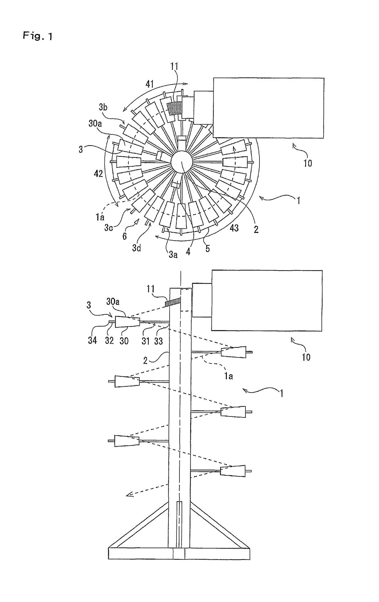
[0034]Embodiments of the present invention will be described below with reference to the drawings. FIG. 1 is a plan view and a front view showing an entire conveying device. A conveying device 1 of the present invention is for conveying a rubber member 11 extruded in a curved state from an extrusion device 10.

[0035]The extrusion device 10 only needs to extrude the rubber member 11 in the curved state, and various types of extrusion devices can be employed. Examples of the extrusion device 10 include: an extrusion device (device described in JP 2007-237596 A) in which a gear pump which sends out rubber extruded from an extrusion machine to a molding base is configured by a helical gear, and a rubber member extruded from the molding base is curved; an extrusion device (device described in JP 2008-246880 A) in which lengths of a pair of opposed lands in a molding base are made different from each other, thereby curving a rubber member which is extruded from the molding base; and an ext...


PUM

PropertyMeasurementUnit
outer diameteraaaaaaaaaa
speedaaaaaaaaaa
conveying speedaaaaaaaaaa

Abstract

A conveying device for conveying a rubber member extruded in a curved state from an extrusion device, the device including a support and a plurality of rollers which are spirally arranged around the support to constitute a spiral conveying path and which rotate while supporting a lower surface of the rubber member, wherein an outer diameter of each of the rollers increases from one end to the other end in an axial direction, the one end being rotatably fixed to the support, and the plurality of rollers include drive rollers which rotate and drive.

Description

BACKGROUND OF THE INVENTION[0001]Field of the Invention[0002]The present invention relates to a conveying device for conveying a rubber member extruded in a curved state from an extrusion device.[0003]Description of the Related Art[0004]In the manufacture of pneumatic tires, the following method is frequently used when an annular bead filler is molded. That is, a bead filler having a predetermined cross-sectional shape is straightly extruded, the bead filler is wound around an outer peripheral side of a bead wire, and ends thereof are bonded to each other. However, when the bead filler is wound around the bead wire, a tensile force is generated due to a difference between an inner periphery and an outer periphery of the bead filler, and the tensile force causes problems that the outer periphery of the bead filler is bent or thinned, the bonded portion is peeled off, and cut rubber is generated.[0005]In order to solve these problems, in JP 2002-527269 A, a straightly extruded bead fi...

Claims


Application Information

Patent Timeline
Patent Type & Authority Patents(United States)
IPC IPC(8): B65G13/02B29D30/48B65G13/08B26D7/06B26D7/02B26D1/04B29C48/355B29C48/92B29K7/00
CPCB29C47/34B26D7/02B26D7/0666B29C47/0004B29C47/0035B29C47/92B65G13/08B65G13/02Y10T83/6582B26D1/04B29C47/0066B29D30/48B29K2007/00B29C48/355B29C48/022B29C48/92B29C48/131B29C48/0022
Inventor MIYAMOTO, RYOSHITSUBOTANI, SOUSUKE
Owner TOYO TIRE & RUBBER CO LTD
Why Eureka
Try Eureka