System for and method of performing Laser Shock Peening on a target with a fluid flow path sandwiched between a transparent to laser light solid medium and the target

a laser shock and fluid flow path technology, applied in laser beam welding apparatus, manufacturing tools, welding apparatus, etc., can solve the problems of affecting the operative life of components, fatigue loads, plastically affected regions, and the depth and magnitude of plastically affected regions when using lsp far exceed those of conventional sp, so as to optimise the shock effect, reduce plasma, and accurate control of the thickness of confinement layer

Active Publication Date: 2019-02-05
UNIVERSITY OF THE WITWATERSRAND
View PDF12 Cites 2 Cited by
  • Summary
  • Abstract
  • Description
  • Claims
  • Application Information

AI Technical Summary

Benefits of technology

[0023]wherein the fluid flow path is sandwiched between the solid medium and the target in use during the laser shock peening process so that the fluid is in direct contact with the solid medium and the target, thereby eliminating any air-fluid interface in the travel path of the laser pulse;
[0028]The system may include a second window and an evacuated region between the two windows to prevent plasma breakdown of the laser pulse in air before the pulse reaches the window which is in contact with the fluid layer. In this embodiment the evacuated region is preferably about 300 mm in length.
[0030]The system may further include means for detecting a first bubble oscillation period of the plasma / vapour bubble generated after the laser pulse striking the target. Such means for detecting first bubble oscillation period may also include means for recording the first bubble oscillation period. The first bubble oscillation period of the cavitation event may be related to the energy delivered to the target, thereby enabling a process diagnostic technique.
[0035]supplying a fluid into a fluid flow path arranged between the solid medium and the contact surface of the target so that the fluid is in direct contact with the solid medium and the target to eliminate any air-fluid interface in the travel path of the laser pulse;

Problems solved by technology

There are primarily three factors that affect the operative life of a component, namely fatigue loads, wear, and corrosion.
However, the depth and magnitude of the plastically affected region when using LSP far exceed those of conventional SP.
Although conventional SP is a well-established technique, it is limited in its range of applications due to a shallow affected depth of the plastically deformed region and a resultant relatively rough surface finish of the component.
However the increase in surface roughness may not be feasible for some applications such as the treatment of turbine blades, for example.
In addition, the surface degradation may reduce some potential for increased fatigue performance.
One of the problems experienced with using a thin water layer or spray as a confinement layer is that air breakdown may occur before the air / water interface.
The occurrence of air breakdown results in an unknown amount of energy being delivered to the target, thereby reducing process robustness.
In other words, the fact that the thin layer of water must be given sufficient time to recover before the next laser shot can be fired limits the frequency at which the laser shots can be fired at the target.
Turning now to the prior art method of submerging a component under water, an obvious problem with this method is the size limitations placed on the component by the size of the water bath.
Accordingly, in a LSP process employing this method, the range of components that are treatable is limited as some components can simply be treated due to their shape and dimensions.

Method used


Image

  • System for and method of performing Laser Shock Peening on a target with a fluid flow path sandwiched between a transparent to laser light solid medium and the target
  • System for and method of performing Laser Shock Peening on a target with a fluid flow path sandwiched between a transparent to laser light solid medium and the target
  • System for and method of performing Laser Shock Peening on a target with a fluid flow path sandwiched between a transparent to laser light solid medium and the target

Examples


first embodiment

[0089]Referring to the drawings, in which like numerals indicate like features, a non-limiting example of a system for performing Laser Shock Peeing (LSP) on a target in accordance with the invention is generally indicated by reference numeral 10.

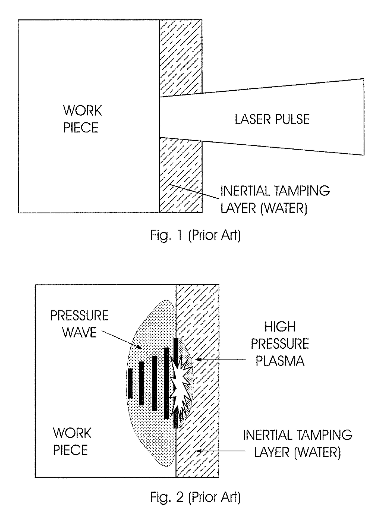
[0090]The system 10 has specifically been developed in the effort to induce a strong secondary shockwave or cavitation event by imposing a thick fluid layer over a surface 102 of a component being treated in the LSP process.

[0091]The system 10 includes a device for generating and transmitting a laser pulse to the target, which is indicated in FIG. 19 by the numeral 100. The device for generating and transmitting a laser pulse is not illustrated in FIG. 19 but is typically a laser capable of transmitting laser pulses, such as 1064 and 532 nm pulses, for example. In use, the laser would typically deliver a continues stream of laser pulses so as to create a laser beam, which is indicated by the numeral 12 in FIG. 19. The laser generating devic...

second embodiment

[0099]Yet another embodiment of the system according to the invention is illustrated in FIG. 21 in which it is indicated by the reference numeral 50. The system 50 is again similar to the system 10 and, again, like numerals indicate like features.

[0100]In this third embodiment of the system 50 the laser window is replaced by a lens 52. When using a laser window such as in the first and second embodiments of the system, the water cavity 26 needs to be long enough such that the focused beam incident on the laser window does not exceed its damage threshold. However, it has been found that it more desirable to keep the water cavity length 30 as short as possible, yet sufficient to obtain a secondary shockwave or cavitation event, in order to minimise water transmission losses. Therefore, the configuration of the third embodiment of the system 50 as illustrated in FIG. 21, addresses the problem of water transmission losses seeing that the laser beam incident upon the lens 52 is not focu...

third embodiment

[0101]In this third embodiment the system 50 includes a body 54 defines two inlets 56.1 and 56.2 feeding water into the fluid chamber 26. From FIG. 21 it can be seen that the fluid inlets 56.1 and 56.2 are located on opposite sides of the fluid chamber 26. It is envisaged that the water inlets 56.1 and 56.2 could be located radially opposite one another in the body 26.

[0102]Yet a further embodiment of the system according to the invention is illustrated in FIG. 21 in which it is indicated by the reference numeral 60. Again, like numerals indicate like features.

[0103]The system 60 in accordance with this fourth embodiment of the invention includes a body 62 which defines an internal cavity 64. As shown in FIG. 22, the internal cavity 64 is provided between two laser windows 66.1 and 66.2 which are located in the end regions of the body 62. An evacuated region is created between the two high power laser windows 66.1 and 66.1 in an attempt to prevent plasma breakdown of the laser pulse...


PUM

PropertyMeasurementUnit
thicknessaaaaaaaaaa
temperatureaaaaaaaaaa
thicknessaaaaaaaaaa

Abstract

The invention is concerned with a system for performing Laser Shock Peeing on a target (100). The system includes a device (10) for generating and transmitting a laser pulse to the target (100) and a fluid source for supplying a fluid into a fluid flow path arranged between an inlet (20) and an outlet (22.1, 22.2). A solid medium (14), which is transparent to incident laser light (12), is located in the laser path so as to allow the laser pulse to pass through it. In use, the fluid flow path is sandwiched between the solid medium (14) and the target (100) during the laser shock peening process so that the fluid is in direct contact with the solid medium (14) and the target (100), thereby eliminating any air-fluid interface in the travel path of the laser pulse. The fluid is also supplied into the fluid flow path having a constant thickness such that a second shock event through cavitation in the fluid layer occurs upon the collapse of a plasmalvapor bubble generated after the laser pulse striking the target. The invention also concerns a method of performing Laser Shock Peeing using the system in accordance with the invention and, in particular, the use of the first bubble oscillation period to determine the amount of energy being delivered to the target (100). The monitoring of the energy being delivered to the target (100) provides for process diagnostics during the LSP procedure.

Description

[0001]The present application is a U.S. National Phase filing of International Application No. PCT / IB2014 / 060814, filed on Apr. 17, 2014, designating the United States of America and claiming priority to South African Patent Application No. 2013 / 02835, filed Apr. 19, 2013, and this application claims priority to and the benefit of the above-identified applications, which are all incorporated by reference herein in their entireties.BACKGROUND TO THE INVENTION[0002]This invention relates to an apparatus and method for performing Laser Shock Peening (LSP). In particular, but not exclusively, the invention relates to the use of a first bubble oscillation period of a cavitation event in determining the effective energy conversion during a Laser Shock Peening (LSP) process.[0003]Conventional Shot Peening (SP) is a cold working process by which compressive residual stresses are introduced into a surface layer of a metal material to improve the mechanical properties. The process of SP typic...

Claims


Application Information

Patent Timeline
Patent Type & Authority Patents(United States)
IPC IPC(8): B23K26/14B23K26/356B23K26/18B23K26/02B23K26/067C21D7/06B23K26/146B23K26/03C21D1/09C21D10/00
CPCC21D10/005B23K26/02B23K26/03B23K26/067C21D7/06B23K26/1476B23K26/18B23K26/356C21D1/09B23K26/146
Inventor GLASER, DANIELPOLESE, CLAUDIA
Owner UNIVERSITY OF THE WITWATERSRAND
Why Eureka
Try Eureka