
Heat pump system, heat pump unit using the same, and method for controlling multiple functional modes thereof

a heat pump and functional mode technology, applied in the field of heat pump systems, can solve the problems of affecting the performance of air conditioning in the heat pump system, the functional modes of the heat pump system are neither mature, nor highly efficient, and the cost of elements and parts is much higher, so as to improve the efficiency, the effect of reducing the number of elements and parts used by the heat pump unit and enhancing the system functions

Active Publication Date: 2019-02-05
CARRIER CORP
View PDF55 Cites 3 Cited by
  • Summary
  • Abstract
  • Description
  • Claims
  • Application Information

AI Technical Summary

Benefits of technology

The present invention provides a heat pump system with multiple functional modes such as high-performance air conditioning and water heating modes. By improving the system structures, the heat pump system runs multiple functional modes which enhances functions of the system and increases the efficiency. The heat pump unit using the heat pump system has simple outdoor pipeline structures, requests a smaller amount of parts, and reduces the cost and complexity for laying pipelines. The method according to the present invention can switch among multiple working modes simply by controlling to power on / off the multi-way valve and the electromagnetic valve, which is quite simple and highly efficient.

Problems solved by technology

Thus, if a user only needs a conventional air conditioning mode, instead of the water heating mode, the air conditioning performance is affected in the heat pump system.
Therefore, functional modes of the heat pump system are neither mature, nor highly efficient.
As a result, on one hand, it has a much higher cost of elements and parts.
On the other hand, it further increases complexity on laying pipelines and increases labor cost.
What's worse, the more complicated the systems are, the more professional and difficult the repairing and maintenance work will be, so that the heat pump unit is rather inconvenient for being used by users.

Method used


Image

  • Heat pump system, heat pump unit using the same, and method for controlling multiple functional modes thereof
  • Heat pump system, heat pump unit using the same, and method for controlling multiple functional modes thereof

Examples


Embodiment Construction

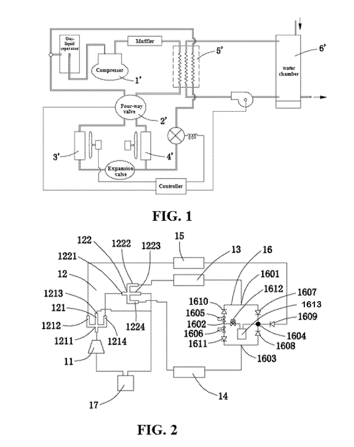
[0032]As shown in FIG. 2, according to an embodiment, the present invention provides a heat pump system 1. The heat pump system 1 includes a compressor 11, a multi-way valve 12, a first heat exchanger 13, a second heat exchanger 14, a heat-recovery-type heat exchanger 15, throttling elements 1612, and a mode-switching flow path 16.

[0033]The mode-switching flow path 16 is disposed with a first flow path, a second flow path, a third flow path, and a fourth flow path each having the throttling element 1612. Each of the flow paths can be controllably turned on or off to implement different functional modes. In a cooling mode, a cooling medium sequentially circulates through an outlet of the compressor 11, the multi-way valve 12, the first heat exchanger 13, the first flow path of the mode-switching flow path 16, the second heat exchanger 14, and the multi-way valve 12, and reaches an inlet of the compressor 11. And / or in a heating mode, the cooling medium sequentially circulates through...


PUM


Abstract

A heat pump system, a controlling method thereof, and a heat pump unit using the heat pump system. The heat pump system includes a compressor, a first heat exchanger, a second heat exchanger, a heat-recovery-type heat exchanger, a multi-way valve, a throttling element, and a mode-switching flow path, which has both air conditioning and water heating functions. By switching the multi-way valve and powering on / off electromagnetic valves in the heat pump system, the controlling method controls the heat pump system to implement multiple functional modes. Furthermore, the heat pump unit using the heat pump system provides multiple functions simply by laying a small amount of parts and elements and pipelines outdoors, thereby greatly reducing the engineering cost and cost of parts, and ensuring a much higher water heating efficiency.

Description

BACKGROUND[0001]Technical Field[0002]The present invention relates to a heat pump system, and more particularly to a heat pump system having multiple functional modes such as an air conditioning mode, a water heating mode, etc.[0003]Related Art[0004]U.S. Pat. No. 4,766,734A has disclosed a heat pump system with a water heating function. As shown in FIG. 1, the heat pump system includes a compressor 1′, a four-way valve 2′, an evaporator 3′, a throttling element and a condenser 4′, and so on. In order to further provide the water heating function, generally, a heat exchanger 5′ is further disposed on a pipeline connected with an outlet of the compressor. The water in a water chamber 6′ is guided to the heat exchanger 5′ for heat exchanging, to generate hot water with a higher temperature. In the heat pump system, high-temperature refrigerants discharging from the outlet of the compressor 1′ all pass through the heat exchanger 5′ and exchange heat with the water, so that the refrigera...

Claims


Application Information

Patent Timeline
Patent Type & Authority Patents(United States)
IPC IPC(8): F25B13/00F24H4/04F24D19/10F24D11/02F25B41/20F25B41/31
CPCF25B13/00F24D11/0214F24D19/1039F24H4/04Y02B30/125F25B2313/0272F25B2313/02742Y02A30/62F24D2200/123Y02A30/60Y02B30/12
Inventor LI, HAIJUNWANG, WEIJUANSHEN, GUANGYU
Owner CARRIER CORP
Learn More